ТУРБОНАГНЕТАТЕЛЬ СНЯТИЕ

-
DISCONNECT CABLE FROM NEGATIVE BATTERY TERMINAL
-
REMOVE ENGINE UNDER COVER NO.1 (w/ Engine Under Cover No.1)
-
REMOVE ENGINE UNDER COVER NO.2 (w/ Engine Under Cover No.2)
-
Remove the engine under cover No.2 together with the engine side under cover LH and engine side under cover RH (for Wide Body).
-
-
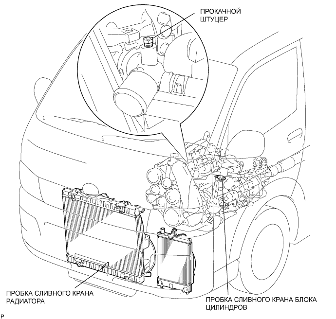
DRAIN ENGINE COOLANT
CAUTION:
Не снимайте пробку радиатора, пока двигатель и радиатор не остынут. Выброс горячей охлаждающей жидкости и пара под давлением может стать причиной серьезных ожогов.
-
Снимите пробку радиатора.
-
Ослабьте пробку сливного крана радиатора и пробку сливного крана системы охлаждения на блоке цилиндров. Затем слейте охлаждающую жидкость.
-
-
REMOVE BATTERY SERVICE HOLE COVER (w/ Sub Battery)
-
REMOVE FRONT DOOR SCUFF PLATE RH
-
REMOVE FRONT SEAT ASSEMBLY RH (for Hi-back Seat Type)
Tech Tips
Use the same procedures described for the LH side. Click here
-
REMOVE FRONT SEAT ASSEMBLY RH (for Low-back Seat Type)
Tech Tips
Use the same procedures described for the LH side. Click here
-
REMOVE ENGINE SERVICE HOLE SUB COVER SUB-ASSEMBLY
-
Заверните коврик, выверните 5 болтов и снимите дополнительную крышку технологического отверстия двигателя.
-
-
REMOVE FENDER APRON MUDGUARD SEAL RH
-
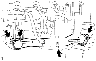
REMOVE EXHAUST PIPE ASSEMBLY FRONT (for Long Wheelbase)
-
Выверните 4 болта, отверните 2 гайки и снимите 2 пружины сжатия. 2 прокладки и приемную трубу в сборе.
-
Отсоедините опору выпускной трубы и снимите приемную трубу в сборе и 2 прокладки.
-
-
REMOVE EXHAUST PIPE ASSEMBLY FRONT (for Super Long Wheelbase)
-
Выверните 4 болта, отверните 2 гайки и снимите 2 пружины сжатия. Снимите приемную трубу в сборе и 2 прокладки.
-
Отсоедините опору выпускной трубы и снимите приемную трубу в сборе и 2 прокладки.
-
-
REMOVE TURBINE OUTLET ELBOW
-
Remove the 4 nuts and the turbine outlet elbow.
-
-
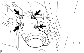
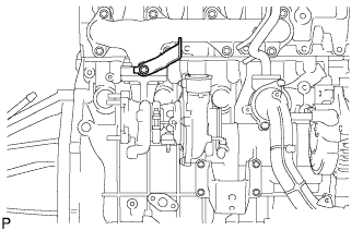
REMOVE TURBOCHARGER STAY
-
Remove the 3 bolts and the turbocharger stay.
-
-
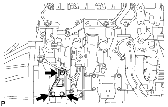
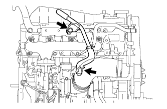
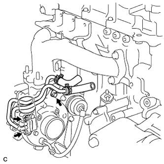
REMOVE TURBO OIL INLET PIPE SUB-ASSEMBLY
-
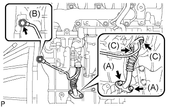
Remove the 2 bolts and the turbo oil inlet pipe from the cylinder block. (A)
Tech Tips
Place a container under the connection before disconnecting the turbo oil inlet pipe because oil in the pipe may spill out.
-
Remove the 2 bolts and the turbo oil inlet pipe from the turbocharger. (C)
-
Remove the union-bolt and gasket from the turbo oil inlet pipe. (B)
-
Remove the 2 gaskets.
-
-
REMOVE FAN & GENERATOR V BELT
-
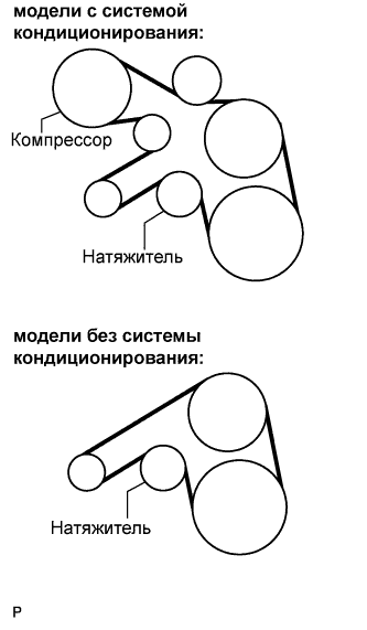
Снимите приводной ремень, повернув шкив натяжителя по часовой стрелке с помощью установочного болта шкива, чтобы ослабить натяжение ремня.
-
-
SEPARATE COMPRESSOR AND MAGNETIC CLUTCH (w/ Air Conditioning)
-
Отсоедините разъем.
-
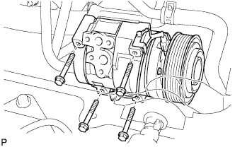
Выверните 4 болта и снимите компрессор и электромагнитную муфту.
-
-
REMOVE COMPRESSOR BRACKET (w/ Air Conditioning)
-
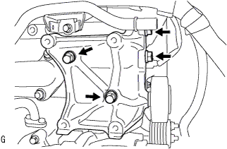
Выверните 4 болта и снимите кронштейн компрессора.
-
-
REMOVE VENTILATION PIPE
-
Loosen the clip, and disconnect the ventilation hose.
-
Remove the bolt and the ventilation pipe.
-
-
REMOVE AIR TUBE ASSEMBLY
-
Remove the 2 clamps, 2 bolts and air tube assembly.
-
-
REMOVE AIR CLEANER HOSE ASSEMBLY
-
Remove the bolt and air cleaner hose assembly.
-
-
REMOVE COMPRESSOR OUTLET ELBOW
-
Remove the 2 bolts and 2 clamps, then remove the compressor outlet elbow.
-
-
REMOVE COMPRESSOR ELBOW STAY
-
Remove the bolt and the compressor elbow stay.
-
-
REMOVE WATER BY-PASS PIPE SUB-ASSEMBLY NO.2
-
Water cooled turbocharger (w/ heater)
-
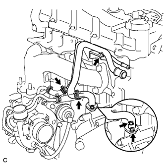
Disconnect the clip and the heater water inlet hose E.
-
Disconnect the clip and the water by-pass hose No.3.
-
Disconnect the 2 clips and the 2 water hoses.
-
Remove the 2 nuts, bolts and water bypass pipe No.2.
-
Remove the gasket.
-
-
Water cooled turbocharger (w/o heater)
-
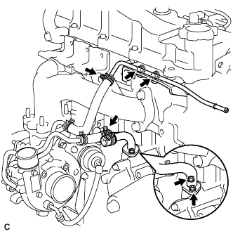
Disconnect the clip and the water by-pass hose No.3.
-
Disconnect the 2 clips and the 2 water hoses.
-
Remove the 2 bolts and the turbo water pipe No.2.
-
Remove the 2 nuts and water by-pass pipe No.2.
-
Remove the gasket.
-
-
Air cooled turbocharger (w/o heater)
-
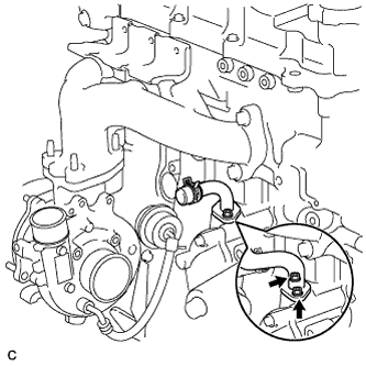
Remove the 2 nuts and water by-pass pipe No.2.
-
Remove the gasket.
-
-
-
REMOVE TURBO WATER PIPE SUB-ASSEMBLY NO.2
-
Remove the bolt, 2 nuts and the turbo water pipe.
-
-
REMOVE TURBOCHARGER SUB-ASSEMBLY
-
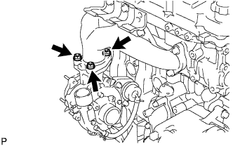
Remove the 3 bolts and the turbocharger.
-
Remove the gasket.
-