- Click here
INSTALL FUEL SENDER GAUGE ASSEMBLY
-
Install the fuel hose grommet to the fuel tank assembly.
-
Install a new fuel suction tube set gasket, fuel pump gauge retainer and fuel sender gauge assembly with the 8 bolts.
4.0 N*m 41 kgf*cm 32 in.*lbf -
Install the fuel tank wire, fuel evaporation No.1 tube sub-assembly, fuel tank main tube sub-assembly and fuel tank return tube sub-assembly to the fuel sender gauge assembly.
-
- Click here
INSTALL FUEL TANK ASSEMBLY
-
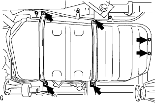
Using the transmission jack, install the 2 fuel tank band sub-assemblies and fuel tank assembly with the 6 bolts.
39 N*m 398 kgf*cm 29 ft.*lbf -
Connect the parking brake cable No.3 with the blot.
15 N*m 148 kgf*cm 11 ft.*lbf
-
- Click here
CONNECT FUEL HOSE NO.3
-
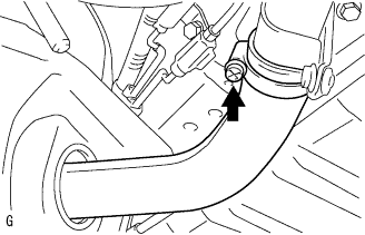
Connect the fuel hose No.3, and tighten the clamp bolt.
-
- Click here
CONNECT FUEL TANK BREATHER TUBE
-
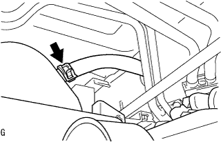
Connect the fuel tank breather tube and install the clip.
-
- Click here
CONNECT FUEL TANK MAIN TUBE SUB-ASSEMBLY
-
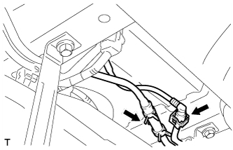
Connect the fuel tank main tube sub-assembly and install the clip.
-
- Click here
CONNECT FUEL TANK RETURN TUBE SUB-ASSEMBLY
-
Connect the fuel return tube sub-assembly (Click here).
-
- Click here
CONNECT FUEL TANK WIRE
-
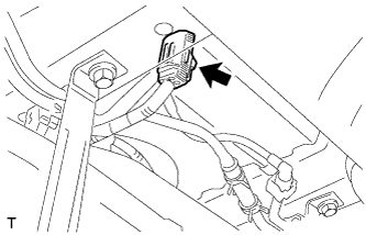
Connect the fuel tank wire.
-
- Click here
INSTALL PROPELLER SHAFT ASSEMBLY
Tip:
-
Propeller shaft assembly for Super Long Wheelbase (Click here).
-
Propeller shaft assembly for Long Wheelbase (Click here).
-
- Click here
CHECK FOR FUEL LEAKS
-
Check that there are no fuel leaks anywhere on the fuel system after doing maintenance.
Tip:When checking for fuel leaks, make sure that there is pressure in the fuel line.
-