ТОПЛИВНЫЙ НАСОС УСТАНОВКА

-
INSTALL INJECTION OR SUPPLY PUMP ASSEMBLY
-
Confirm that the supply pump gear in the timing gear case moves back and forth smoothly.
-
Install a new O-ring and the pulley key to the supply pump.
-
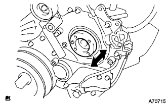
Aligning the projecting edge of the supply pump head to the key-slot of the supply pump gear, install the pump to the timing gear case.
-
While holding the supply pump by hand, push the supply pump gear rearward to engage the pump gear and drive shaft.
-
Temporarily install the supply pump with the 2 nuts.
-
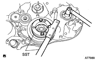
Using SST, hold the crankshaft.
- SST
- 09213-58013
- 09330-00021
-
Install the supply pump gear set nut.
Tech Tips
Set a new O-ring before tightening the supply pump gear set nut.
- Torque:
- 64 N*m { 653 kgf*cm, 47 ft.*lbf }
-
Temporarily install the supply pump stay with the 2 bolts on the engine block side.
-
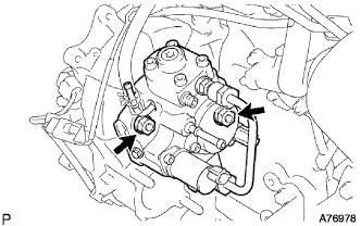
Tighten the 2 nuts for the injection pump.
- Torque:
- 21 N*m { 214 kgf*cm, 16 ft.*lbf }
-
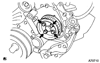
Install the camshaft timing pulley flange No.2 and pump drive shaft pulley with the 4 bolts.
- Torque:
- 31 N*m { 316 kgf*cm, 23 ft.*lbf }
-
-
CHECK PUMP DRIVE SHAFT THRUST CLEARANCE
-
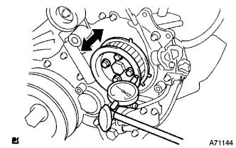
Push the pump drive shaft pulley back and forth to check a thrust clearance of the injection pump drive shaft.
Thrust clearance 0.15 to 0.55 mm (0.0059 to 0.0217 in.) Note
Make sure that the crankshaft pulley's notch is at 30 degree in the counterclockwise direction form the TDC position.
Tech Tips
If there is not thrust clearance, disassemble and reassemble the injection pump and pump drive shaft pulley.
-
-
INSTALL FUEL INLET PIPE SUB-ASSEMBLY
Note
-
When replacing the fuel supply pump, common rail, cylinder block, cylinder head, cylinder head gasket, or timing gear case with a new one, replace the fuel inlet pipe.
-
Be careful not to adhere dusts, dirt or any other materials onto the joint area of the fuel inlet pipe.
-
Temporarily install the fuel inlet pipe.
-
Using SST, tighten the injection pipe on the common rail side.
- SST
- 09023-12701
- Torque:
- 32 N*m { 326 kgf*cm, 24 ft.*lbf, for use with SST }
-
Using SST, tighten the injection pipe on the supply pump side.
- SST
- 09023-12701
- Torque:
- 32 N*m { 326 kgf*cm, 24 ft.*lbf, for use with SST }
-
-
INSTALL INJECTION PIPE
- SST
- 09023-12701
Note
-
When replacing the fuel injector, common rail, or cylinder head with a new one, replace injection pipes No. 1, No. 2, No. 3, and No. 4.
-
Keep clean the joint of the injection pipe.
-
Install the injection pipes.
-
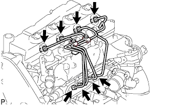
Temporarily install the 4 injection pipes.
-
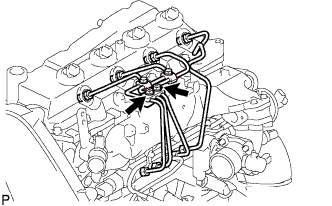
Install the injection pipe clamp No.3 in 2 nuts.
- Torque:
- 5.0 N*m { 51 kgf*cm, 44 in.*lbf }
-
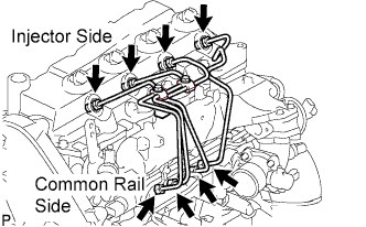
Fasten the union sequentially, from the injection pipe common rail to the injector, using SST.
- SST
- 09023-12701
- Torque:
- Use union nut wrench and torque wrench
- 32 N*m { 326 kgf*cm, 24 ft.*lbf }
-
-
INSTALL OIL LEVEL GAGE GUIDE
-
Установите на трубку щупа проверки уровня масла новое уплотнительное кольцо.
-
Нанесите на уплотнительное кольцо тонкий слой моторного масла.
-
Установите трубку щупа проверки уровня масла и закрепите ее болтом.
- Torque:
- 8,0 Н*м { 82 кгс*см, 71 фунт-сила-дюйм }
-
Установите щуп проверки уровня масла.
-
-
INSTALL INTAKE AIR CONNECTOR (w/o EGR Valve)
-
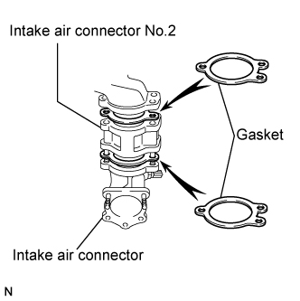
Temporarily install 2 new gaskets and intake air connector No.2 to the intake air connector.
-
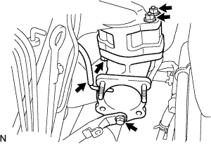
Temporarily tighten the intake air connector assembly with the bolt and 2 nuts.
-
Tighten the manifold stay with the bolt.
-
Tighten the intake air connector with the bolt and 2 nuts.
-
Install the vacuum hose to the intake air connector.
-
-
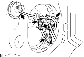
TEMPORARILY TIGHTEN ELECTRIC EGR CONTROL VALVE ASSEMBLY (w/ EGR Valve)
-
Temporarily tighten the EGR valve assembly with the sensor.
-
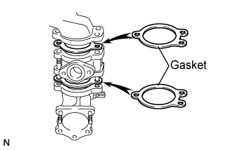
Install 2 new gaskets and the EGR valve to the intake air connector as shown in the illustration.
-
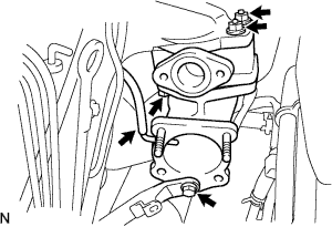
Temporarily tighten the intake air connector with EGR valve assembly to the intake manifold with the bolt and the 2 nuts.
-
Install the vacuum hose to the intake air connector.
-
Temporarily tighten the manifold stay with the bolt.
-
Connect the EGR valve position sensor connector.
-
Connect the intake air temperature sensor connector.
-
-
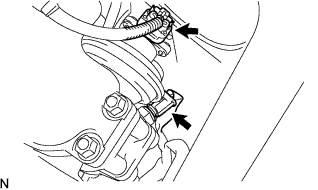
Install the vacuum regulating valve.
-
Install the vacuum regulating valve with the 2 bolts.
- Torque:
- 20 N*m { 204 kgf*cm, 15 ft.*lbf }
-
Connect the 2 vacuum hoses and the regulating valve connector.
-
-
-
INSTALL EGR PIPE SUB-ASSEMBLY NO.1 (w/ EGR Valve)
-
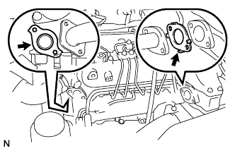
Install the 2 gaskets to the cylinder head and EGR pipe sub-assembly as shown in the illustration.
-
Install the EGR pipe sub-assembly with the 2 bolts and 2 nuts.
- Torque:
- 13 N*m { 133 kgf*cm, 10 ft.*lbf }
-
Tighten the intake air connector with the bolt and the 2 nuts.
- Torque:
- 20 N*m { 204 kgf*cm, 15 ft.*lbf }
-
Tighten the manifold stay.
- Torque:
- 19 N*m { 194 kgf*cm, 14 ft.*lbf }
-
-
REMOVE EGR PIPE SUB-ASSEMBLY NO.1 (w/ EGR Valve)
-
Remove the 3 bolts, the 2 nuts, and the EGR pipe sub-assembly.
-
Remove the 2 gaskets.
-
-
INSTALL DIESEL THROTTLE BODY ASSEMBLY
Note
After removing and installing, or replacing the throttle body, be sure to perform the operation check.
-
Install a new gasket to intake air connector.
-
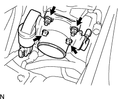
Install the throttle body with the 2 bolts and the 2 nuts.
- Torque:
- 20 N*m { 204 kgf*cm, 15 ft.*lbf }
-
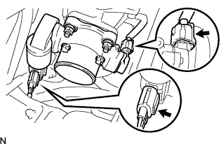
Connect the 2 throttle body connectors.
-
-
INSTALL AIR HOSE NO.4
-
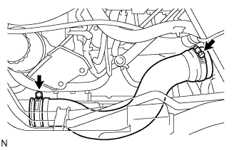
Install the air hose No.4 with the 2 clamps.
- Torque:
- 6.0 N*m { 61 kgf*cm, 53 in.*lbf }
-
-
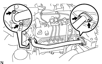
INSTALL EGR PIPE SUB-ASSEMBLY NO.1 (w/ EGR Valve)
-
Install 2 new gaskets to the cylinder head and the EGR pipe sub-assembly No.1 as shown in the illustration.
-
Install the EGR pipe with the 2 bolts and the 2 nuts.
- Torque:
- 13 N*m { 133 kgf*cm, 10 ft.*lbf }
-
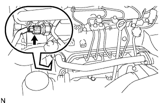
Connect the fuel pressure sensor connector.
-
-
INSTALL OIL RETURN HOSE (w/ Inter cooler)
-
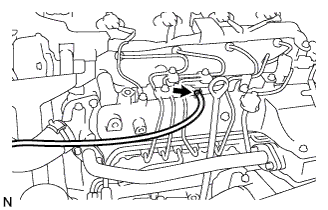
Connect the oil return hose with the clip.
-
-
INSTALL VANE PUMP OIL RESERVOIR ASSEMBLY
-
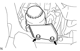
Install the vane pump oil reservoir assembly with the 2 bolts.
- Torque:
- 8.0 N*m { 82 kgf*cm, 71 in.*lbf }
-
-
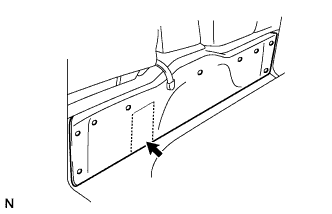
INSTALL ENGINE SERVICE HOLE COVER NO.2
-
Install the engine service hole cover No.2 with the 3 bolts.
- Torque:
- 13 N*m { 133 kgf*cm, 10 ft.*lbf }
-
Return the carpet.
-
-
INSTALL TIMING BELT
-
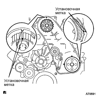
Удостоверьтесь, что установочные метки совмещены, как показано на рисунке.
-
Установите приводной ремень газораспределения на шкив приводного вала насоса, зубчатое колесо распредвала и опорный ролик приводного ремня газораспределения № 1, придерживаясь этой последовательности.
-

Установите натяжитель вертикально на пресс.
Note
-
Не допускайте царапания и деформирования конца толкателя.
-
Запрессуйте толкатель натяжителя.
-
Обеспечьте защиту конца толкателя от повреждений ветошью.
-
-
С помощью пресса медленно запрессуйте толкатель с усилием 981 - 9807 Н (100 - 1000 кгс, 220 - 2205 фунт-силы).
Note
Не прикладывайте к толкателю усилие свыше 981 - 9807 Н (100 - 1000 кгс, 220 - 2205 фунт-силы).
-
Совместите отверстия в толкателе и кожухе. Для сохранения положения установки толкателя пропустите через отверстия шестигранную головку на 1,27 мм.
-
Временно закрепите натяжитель приводного ремня 2 болтами, прижимая опорный ролик к приводному ремню газораспределения.
-
Затяните 2 болта.
- Torque:
- 13 Н*м { 133 кгс*см, 10 фунт-сила-футов }
Note
Равномерно затяните 2 болта и установите натяжитель
-
Выньте из натяжителя торцевой гаечный ключ на 1,5 мм.
-
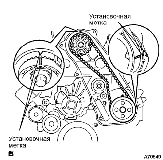
Поверните коленчатый вал по часовой стрелке на два оборота и убедитесь, что установочные метки совмещены, как показано на рисунке.
-
-
INSTALL TIMING BELT COVER NO.1
-
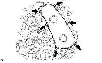
Установите крышку приводного ремня газораспределения № 1 и закрепите ее 6 болтами.
- Torque:
- 6,0 Н*м { 61 кгс*см, 53 фунт-сила-дюйма }
-
Присоедините зажим жгута проводов.
-
-
INSTALL FAN & GENERATOR V BELT
-
Провернув шкив натяжителя поликлинового ремня по часовой стрелке, установите поликлиновой ремень вентилятора и генератора.
Note
Проверьте правильность посадки поликлинового ремня вентилятора и генератора на каждом шкиве.
-
Проверьте метку индикатора натяжителя поликлинового ремня (см. стр. Click here).
-
-
INSTALL ENGINE SERVICE HOLE SUB COVER SUB-ASSEMBLY
-
Установите вспомогательную крышку технологического отверстия двигателя и закрепите ее 5 болтами.
- Torque:
- 13 Н*м { 133 кгс*см, 10 фунт-сила-футов }
-
-
INSTALL FRONT DOOR SCUFF PLATE RH
-
INSTALL FRONT SEAT ASSEMBLY RH (for Hi-back Seat Type)
-
Выполните те же действия, что были описаны выше для противоположной стороны (см. стр. Click here).
-
-
INSTALL FRONT SEAT ASSEMBLY RH (for Low-back Seat Type)
-
Выполните те же действия, что были описаны выше для противоположной стороны (см. стр. Click here).
-
-
CONNECT BATTERY NEGATIVE CABLE
-
BLEED FUEL LINE
-
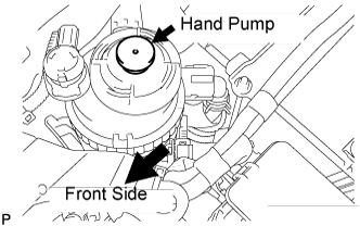
Using the hand pump, bleed air from the fuel system until pumping becomes difficult.
-
-
CHECK FOR FUEL LEAKAGE
-
Если используется портативный диагностический прибор
-
Подсоедините портативный диагностический прибор к DLC3.
-
Установите замок зажигания в положение ON (ВКЛ) и включите питание портативного диагностического прибора.
Note
Не запускайте двигатель.
-
Выберите на портативном диагностическом приборе режим Active Test.
Tech Tips
Более подробная информация приведена в руководстве по эксплуатации портативного диагностического прибора.
-
-
Если портативный диагностический прибор не используется.
-
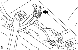
Отсоедините разъем топливного насоса.
-
С помощью технологического провода соедините контакты FP и +B блока реле.
Note
Во избежание нарушения работы системы обратите внимание на место соединения контактов.
-
Установите замок зажигания в положение ON (ВКЛ) и убедитесь, что топливный насос работает.
Note
Не запускайте двигатель.
-
-
После проведения техобслуживания проверяйте отсутствие утечек топлива в топливной системе.
-
Проверьте, поднимается ли винт демпфера пульсаций вверх во время работы топливного насоса.
Если устройство не работает должным образом, проверьте следующие детали и узлы:
-
Плавкая вставка
-
Топливный насос
-
Проводные соединения
-
ECM
-
Предохранители
-
-
Выключите зажигание.
-
Отсоедините портативный диагностический прибор от DLC3.
-