ТОПЛИВНАЯ ФОРСУНКА СНЯТИЕ

-
CHECK INJECTION COMPENSATION CODE
-
Check that the injection compensation code registered in the injector assembly installed on each cylinder match the ones registered in the engine ECU Click here.
-
If they do not match, follow the procedures below to correct the registration details and recheck the symptom.
-
Correct the registration details by following the procedures in "resister injection compensation code" Click here.
-
After correcting the registration details, check if the same symptom occurs as when the vehicle was brought in.
Tech Tips
If it does not occur, the symptom may be caused by errors in injection compensation code registration.
-
-
-
REMOVE BATTERY SERVICE HOLE COVER (w/ Sub-Battery)
-
DISCONNECT BATTERY NEGATIVE CABLE
-
REMOVE ENGINE UNDER COVER NO.1 (w/ Engine Under Cover)
-
DRAIN ENGINE COOLANT
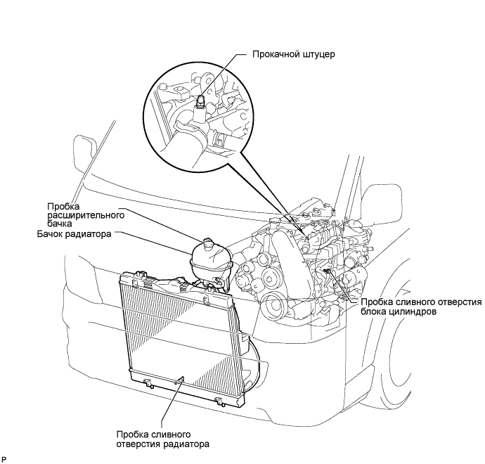
CAUTION:
Для предотвращения ожогов не снимайте пробку расширительного бачка, пока двигатель и радиатор не охладятся. Тепловое расширение вызывает выброс из радиатора горячей охлаждающей жидкости и пара.
-
Ослабьте пробку сливного отверстия радиатора.
-
Снимите пробку расширительного бачка.
-
Ослабьте пробку сливного отверстия блока цилиндров (на крышке масляного радиатора двигателя) и слейте охлаждающую жидкость.
-
Затяните пробку сливного отверстия радиатора.
-
Затяните пробку сливного отверстия блока цилиндров (на крышке масляного радиатора двигателя).
- Torque:
- 8,0 Н*м { 82 кгс*см, 71 фунт-сила-дюйм }
-
-
REMOVE FRONT SEAT ASSEMBLY RH (for Hi-back Seat Type)
-
Perform the same procedure as above on the opposite side. Click here
-
-
REMOVE FRONT SEAT ASSEMBLY RH (for Low-back Seat Type)
-
Perform the same procedure as above on the opposite side. Click here
-
-
REMOVE FRONT DOOR SCUFF PLATE RH
-
DISCONNECT VANE PUMP OIL RESERVOIR ASSEMBLY
-
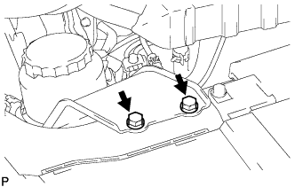
Выверните 2 болта и отсоедините масляный бачок лопастного насоса в сборе.
Note
Подвесьте масляный бачок лопастного насоса в сборе с помощью провода, чтобы не допустить пролива жидкости для механизма рулевого управления с усилителем.
-
-
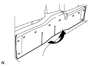
REMOVE ENGINE SERVICE HOLE SUB COVER SUB-ASSEMBLY
-
Roll up the carpet, and remove the engine service hole sub cover assembly.
-
-
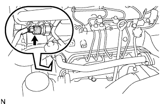
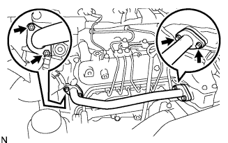
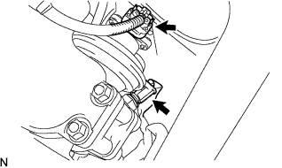
DISCONNECT OIL RETURN HOSE (w/ Inter cooler)
-
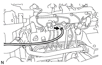
Ослабьте фиксатор.
-
Отсоедините возвратный масляный шланг от впускного коллектора.
-
-
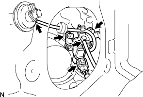
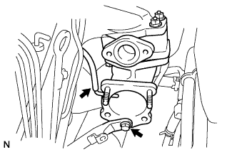
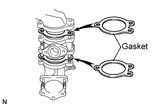
REMOVE EGR PIPE SUB-ASSEMBLY NO.1 (w/ EGR Valve)
-
Отсоедините разъем датчика давления в топливной системе.
-
Выверните 2 болта, отверните 2 гайки и снимите трубу РОГ.
-
Снимите 2 прокладки.
-
-
REMOVE AIR HOSE NO.4
-
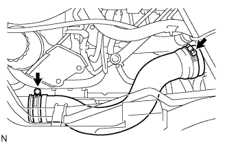
Ослабьте 2 зажима.
-
Снимите воздушный шланг № 4.
-
-
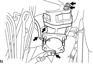
REMOVE DIESEL THROTTLE BODY ASSEMBLY
-
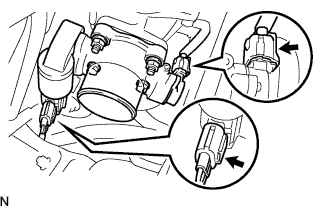
Отсоедините 2 разъема корпуса дроссельной заслонки.
-
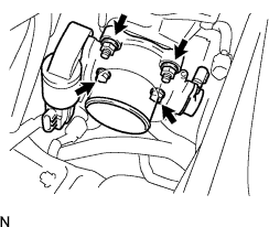
Выверните 2 болта, отверните 2 гайки и снимите корпус дроссельной заслонки дизельного двигателя в сборе.
-
Снимите прокладку с патрубка подачи воздуха.
-
-
REMOVE ENGINE SERVICE HOLE COVER NO.2
-
Roll up the carpet.
-
Remove the 3 bolts and the engine service hole cover No.2.
-
-
REMOVE INTAKE AIR CONNECTOR (w/o EGR Valve)
-
Remove the bolt, and separate the manifold stay.
-
Disconnect the vacuum hose from intake air connector.
-
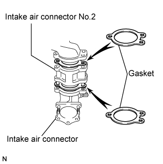
Remove the bolt, 2 nuts and the intake air connector assembly.
-
Remove the 2 gaskets and intake air connector No.2 from the intake air connector.
-
-
REMOVE ELECTRIC EGR CONTROL VALVE ASSEMBLY
-
Remove the vacuum regulating valve.
-
Remove the 2 vacuum hoses and the vacuum regulating valve connector.
-
Remove the 2 bolts and the vacuum regulating valve.
-
-
Remove the EGR valve assembly with the sensor.
-
Remove the bolt, and separate the manifold stay.
-
Disconnect the vacuum hose from the intake air connector.
-
Disconnect the intake air temperature sensor connector.
-
Disconnect the EGR valve position sensor connector.
-
Remove the bolt, 2 nuts and the intake air connector assembly.
-
Remove the 2 gaskets and EGR valve assembly from the intake air connector.
-
-
-
REMOVE OIL LEVEL GAGE GUIDE
-
Remove the oil level gauge.
-
Remove the bolt and oil level gauge guide.
-
-
REMOVE INJECTION PIPE
- SST
- 09023-12701
-
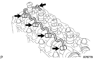
Remove the injection pipe.
-
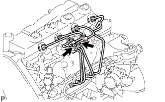
Remove the 2 nuts and injection pipe clamp No.3.
-
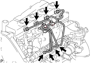
Using SST, remove the 4 injection pipes.
- SST
- 09023-12701
-
-
REMOVE NOZZLE LEAKAGE PIPE ASSEMBLY NO.2
-
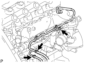
Disconnect 3 fuel hoses from nozzle leakage pipe assembly No.2.
-
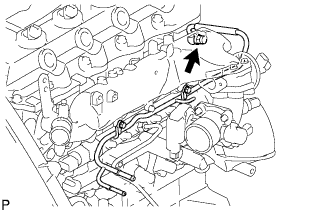
Remove the union bolt from nozzle leakage pipe No.2.
-
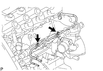
Remove the 2 bolts and nozzle leakage pipe No.2.
-
Remove the gasket from nozzle leakage pipe No.2.
-
-
REMOVE CYLINDER HEAD COVER SUB-ASSEMBLY
-
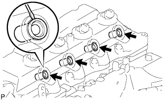
Using a small screwdriver, remove the holder seal by prying the portion between the holder seal and the cutout part of the cylinder head.
-
Disconnect the ventilation hose.
-
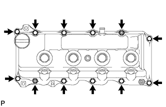
Remove the 10 bolts, 2 nuts, cylinder head cover and the cylinder head cover gasket.
Note
After removing the fuel pipe, put a plastic bag and rubber band to prevent dirt and foreign objects over the injectors inlet.
-
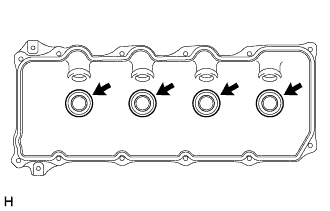
Remove the 4 No. 3 cylinder head cover gaskets from the cylinder head cover.
-
-
REMOVE INJECTOR ASSEMBLY
-
Remove the nozzle leakage pipe assembly.
-
Remove the union bolt, 4 hollow screws, 5 gaskets and nozzle leakage pipe assembly.
Note
Cover the plastic bag prevent to the injector.
-
-
Remove the nozzle holder clamp.
-
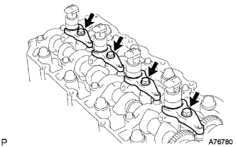
Remove the 4 bolts, washers and 4 nozzle holder clamps.
Note
Be sure to keep separate the removed bolts, washers, and nozzle holder clamps for each cylinder.
-
-
Remove the injector assemblies.
-