- Click here
DRAIN ENGINE COOLANT
-
Снимите пробку радиатора.
CAUTION:Не снимайте пробку радиатора, пока двигатель и радиатор не остынут. Выброс горячей охлаждающей жидкости и пара под давлением может стать причиной серьезных ожогов.
-
Убедитесь, что вокруг пробки и наливной горловины радиатора нет чрезмерных отложений ржавчины и окалины. Охлаждающая жидкость не должна содержать масло.
Tip:При наличии избыточных загрязнений очистите каналы для охлаждающей жидкости и замените охлаждающую жидкость.
-
Установите на место пробку радиатора.
-
- Click here
REMOVE FRONT SEAT ASSEMBLY RH (for Hi-back Seat Type)
Tip:Порядок выполнения работ такой же, как для левой стороны. (см. стр.Click here)
- Click here
REMOVE FRONT SEAT ASSEMBLY RH (for Low-back Seat Type)
Tip:Порядок выполнения работ такой же, как для левой стороны. (см. стр.Click here)
- Click here
REMOVE FRONT DOOR SCUFF PLATE RH
- Click here
REMOVE ENGINE SERVICE HOLE SUB COVER SUB-ASSEMBLY
-
Заверните коврик и снимите крышку технологического отверстия двигателя.
-
- Click here
REMOVE RADIATOR HOSE INLET
- Click here
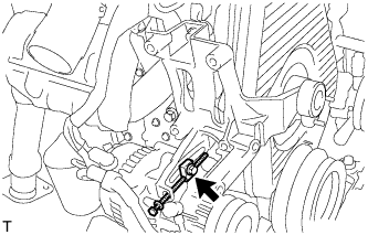
REMOVE VANE PUMP V BELT
-
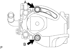
Ослабьте болт А и гайку В и снимите поликлиновой ремень.
-
- Click here
REMOVE V (COOLER COMPRESSOR TO CRANKSHAFT PULLEY) BELT NO.1
-
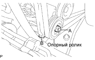
Ослабьте гайку А и болт В и снимите поликлиновой ремень.
-
- Click here
REMOVE FAN AND GENERATOR V BELT (w/o AIR CONDITIONING)
-
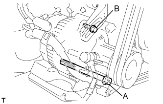
Ослабьте болты А и В и снимите поликлиновой ремень.
-
- Click here
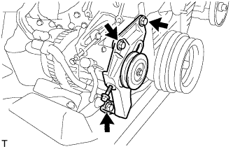
REMOVE FAN AND GENERATOR V BELT (w/ AIR CONDITIONING)
-
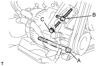
Ослабьте болты A и В.
-
Ослабьте регулировочный болт C и снимите поликлиновой ремень.
-
- Click here
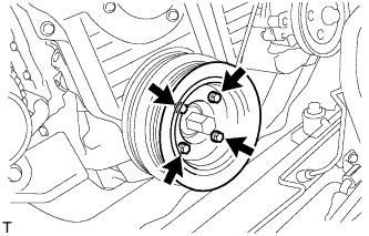
REMOVE FAN PULLEY
-
Remove the 4 nuts, fan spacer and fan pulley.
-
- Click here
REMOVE COMPRESSOR AND MAGNETIC CLUTCH (w/ AIR CONDITIONING)
-
Ослабьте болты A и В.
-
Ослабьте регулировочный болт C и снимите поликлиновой ремень.
-
- Click here
REMOVE COMPRESSOR MOUNTING BRACKET (w/ AIR CONDITIONING)
-
Отверните 3 болта и снимите кронштейн опоры компрессора.
-
Выверните болт и снимите распорную трубку.
-
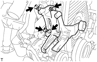
Отверните 4 болта и снимите кронштейн опоры компрессора.
-
- Click here
REMOVE VANE PUMP DRIVE PULLEY
-
w/o Air conditioning:
-
Remove the 4 bolts, vane pump drive pulley and the vane pump drive pulley spacer.
-
-
w/ Air conditioning:
-
Remove the 4 bolts, 2 vane pump drive pulleys.
-
-
- Click here
REMOVE CRANKSHAFT PULLEY
-
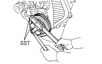
Using SST, remove the pulley bolt.
09213-54015 91651-60855 09330-00021 -
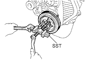
Using SST, remove the pulley.
09950-50013 09951-05010 09952-05010 09953-05020 09954-05021 09950-60010 09951-00490 09950-40011 09957-04010
-
- Click here
REMOVE TIMING CHAIN OR BELT COVER SUB-ASSEMBLY
-
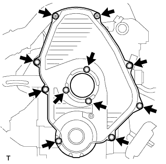
Remove the 11 bolts, washers, timing belt cover and 2 gaskets.
-
- Click here
REMOVE TIMING BELT GUIDE
- Click here
SET NO.1 CYLINDER TO TDC/COMPRESSION
-
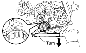
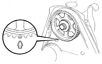
Using the crankshaft pulley bolt, align its groove with the timing pointer by turning the crankshaft clockwise.
-
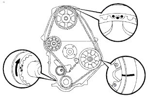
Check that the timing marks of the camshaft timing pulley and No.2 timing belt cover are aligned.
If not, turn the crankshaft 1 revolution (360°).
-
- Click here
REMOVE TIMING BELT
-
Remove the timing belt.
Tip:If reusing the timing belt, draw a direction arrow on the timing belt (in the direction of engine revolution), and place matchmarks on the pulleys and timing belt.
-
Turn the crankshaft 90° counterclockwise, and put the timing mark of the crankshaft timing pulley with the protrusion of the timing gear case.
Note:If the timing belt is disengaged, having the crankshaft timing pulley at the wrong angle can cause the piston head and valve head to come into contact with each other when you remove the camshaft timing pulley, causing damage. So always set the crankshaft pulley at the correct angle.
-
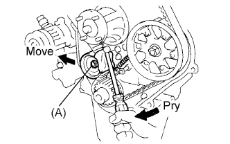
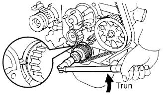
Loosen the timing belt idler No.1 bolt (A), and shift the idler to the left as far as possible.
-
Temporarily tighten the pulley bolt (A), and then relieve the timing belt tension.
-
Remove the timing belt.
-
- Click here
REMOVE AIR CLEANER HOSE NO.2
-
Loosen the bolt, and disconnect the air cleaner hose No.2.
-
- Click here
REMOVE INTAKE AIR CONNECTOR SUB-ASSEMBLY
-
Disconnect the ventilation hose.
-
Disconnect the turbo pressure sensor connector.
-
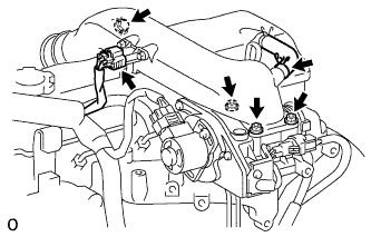
Remove the bolt, 3 nuts, intake air connector and gasket.
-
- Click here
REMOVE VENTURI ASSEMBLY
-
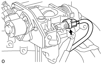
Disconnect the throttle open switch connector.
-
Disconnect the throttle control motor connector.
-
Remove the venturi and gasket.
-
- Click here
REMOVE INJECTION PIPE SET
-
Loosen the 8 union nuts of the 4 injection pipes.
-
Remove the 2 nuts, 2 upper pipe clamps, and 4 injection pipes with lower pipe clamps.
-
- Click here
REMOVE INJECTION PUMP DRIVE PULLEY
-
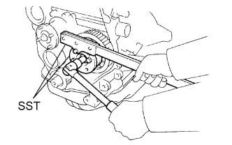
Using SST, remove the pulley nut.
09213-14010 91651-60865 09330-00021 -
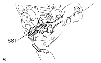
Using SST, remove the drive pulley.
09950-50013 09951-05010 09952-05010 09953-05010 09954-05021
-
- Click here
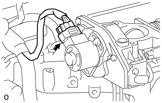
REMOVE INJECTION OR SUPPLY PUMP ASSEMBLY
-
Disconnect the engine speed sensor connector.
-
Disconnect the spill control valve connector.
-
Disconnect the correction unit connector.
-
Disconnect the timer control valve connector.
-
Disconnect the fuel temperature sensor connector.
-
Disconnect the engine wire clamp.
-
Disconnect the 3 fuel hoses.
-
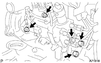
Disconnect the 3 bolts and injection pump stay No.1.
-
Remove the 2 nuts and injection or supply pump assembly.
-