- Click here
INSTALL TENSIONER PULLEY
Note:Perform the following procedure when it is necessary to replace the tensioner pulley.
Tip:The tensioner pulley service kit consists of a bolt, dust seal and tensioner pulley.
-
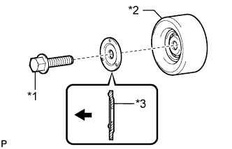
Install the dust seal and bolt to the tensioner pulley as shown in the illustration.
Table 1. Text in Illustration *1 Bolt *2 Tensioner Pulley *3 Dust Seal 
Front Note:
-
The dust seal must be oriented correctly when installed. If the dust seal is installed incorrectly, the bearing may be damaged.
-
Do not touch the seal surface of the bearing.
Tip:Be sure to use the bolt from the service kit.
-
-
Tighten the bolt by hand until the flange of the bolt contacts the dust seal and the tensioner pulley is fixed in place.
Note:Do not use any tools.
-
Tighten the bolt.
47 N*m 479 kgf*cm 35 ft.*lbf
-
- Click here
INSTALL FAN AND GENERATOR V BELT
-
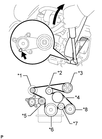
Install the fan and generator V belt to all the pulleys except the V-ribbed belt tensioner pulley.
Table 2. Text in Illustration *1 Generator *2 No. 1 Idler Pulley *3 Vane Pump *4 Fan Pulley *5 Tensioner Pulley *6 Crankshaft Pulley *7 Idler Pulley *8 Cooler Compressor -
Use the hexagon-shaped part indicated by the arrow in the illustration to move the tensioner pulley downward, and then install the fan and generator V belt to the tensioner pulley.
Note:
-
The backside of the fan and generator V belt should face the tensioner pulley.
-
Check that the fan and generator V belt is properly installed to each pulley.
-
-
- Click here
INSPECT FAN AND GENERATOR V BELT
-
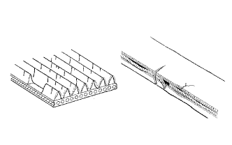
Check the belt for wear, cracks or other signs of damage.
If any of the following defects is found, replace the fan and generator V belt.
-
The belt is cracked.
-
The belt is worn out to the extent that the cords are exposed.
-
The belt has chunks missing from the ribs.
-
-
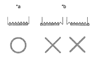
Check that the belt fits properly in the ribbed grooves.
Table 3. Text in Illustration *a CORRECT *b INCORRECT Tip:Check with your hand to confirm that the belt has not slipped out of the grooves on the bottom of the pulley. If it has slipped out, replace the fan and generator V belt. Install a new fan and generator V belt correctly.
-
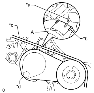
Check that the tensioner indicator mark is within range A shown in the illustration.
Table 4. Text in Illustration *a Bracket Side Indicator *b Arm Side Indicator *c Fan and Generator V Belt *d V-ribbed belt tensioner assembly If the mark is not within range A, replace the fan and generator V belt.
Tip:If a new belt has been installed, check that the tensioner indicator mark is within range A.
-
- Click here
INSTALL ENGINE SERVICE HOLE SUB COVER SUB-ASSEMBLY
-
Install the engine service hole cover sub-assembly with the 5 bolts.
13 N*m 133 kgf*cm 10 ft.*lbf
-
- Click here
INSTALL FRONT DOOR SCUFF PLATE RH
- Click here
INSTALL FRONT SEAT ASSEMBLY RH