РАСПРЕДВАЛ УСТАНОВКА

-
INSTALL CAMSHAFT
-
Set the No.1 cylinder to 90° BTDC/compression.
Tech Tips
Set the No.1 cylinder to 90° BTDC/compression to avoid interference with the piston top and valve head.
-
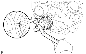
Using the crankshaft pulley bolt, turn the crankshaft, and align the timing mark of the crankshaft timing pulley with the protrusion of the timing gear case.
-
-
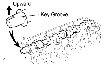
Install the camshaft.
-
Place the camshaft on the cylinder head with the key groove facing upward.
-
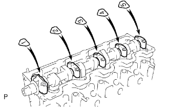
Install the 5 bearing caps in their proper locations.
-
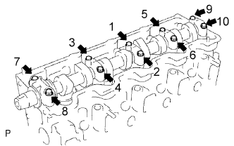
Apply a light coat of engine oil to the threads and under the heads of the bearing cap bolts.
-
Install and uniformly tighten the 10 bearing cap bolts, in several steps, in the sequence shown.
- Torque:
- 25 N*m { 255 kgf*cm, 18 ft.*lbf }
-
-
-
INSTALL OIL SEAL RETAINER, NO.2 OIL SEAL
-
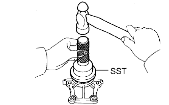
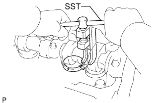
Using SST and a hammer, tap in a new oil seal until its surface is flush with the oil seal retainer edge.
- SST
- 09960-10010 ( 09962-01000, 09963-01000 )
-
Apply MP grease to the oil seal lip.
-
-
INSTALL CAMSHAFT OIL SEAL RETAINER
-
Install a new gasket and the retainer with the 4 bolts.
- Torque:
- 18 N*m { 185 kgf*cm, 13 ft.*lbf }
-
-
INSTALL TIMING BELT COVER NO.2
-
Install the timing belt cover with the 4 bolts.
- Torque:
- 18 N*m { 185 kgf*cm, 13 ft.*lbf }
-
-
INSTALL CAMSHAFT TIMING PULLEY
-
Install the woodruff key to the key groove of the camshaft.
-
Align the pulley set key with the timing mark outward.
-
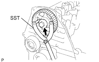
Using SST, install the pulley with the bolt.
- Torque:
- 98 N*m { 1,000 kgf*cm, 72 ft.*lbf }
-
-
INSPECT VALVE CLEARANCE
-
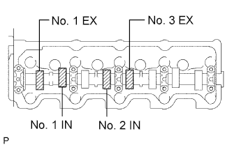
Check only the valves indicated in the illustration.
-
Using a feeler gauge, measure the clearance between the valve lifter and camshaft.
-
Record the out-of-specification valve clearance measurements. They will be used later to determine the required replacement adjusting shim.
Valve clearance (Cold): Intake 0.20 to 0.30 mm (0.008 to 0.012 in.) Exhaust 0.40 to 0.50 mm (0.016 to 0.020 in.)
-
-
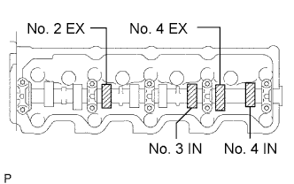
Turn the crankshaft one revolution (360°) and align the mark as above. (See procedure in step 3)
-
Check only the valves indicated in the illustration. Measure the valve clearance. (See procedure in step (a))
Valve clearance (Cold): Intake 0.20 to 0.30 mm (0.008 to 0.012 in.) Exhaust 0.40 to 0.50 mm (0.016 to 0.020 in.)
-
-
ADJUST VALVE CLEARANCE
-
Remove the adjusting shim.
-
Turn the crankshaft so that the cam lobe of the camshaft on the adjusting valve points upward.
-
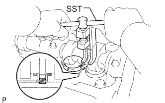
Using SST, press down the valve lifter.
- SST
- 09248-64011
-
Position the notch of the valve lifter with it facing the exhaust manifold side.
-
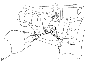
Remove the adjusting shim with a screwdriver and magnetic finger.
-
-
Determine the replacement adjusting shim size by following the formula or charts:
-
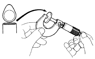
Using a micrometer, measure the thickness of the removed shim.
-
Calculate the thickness of a new shim so that the valve clearance comes within the specified value.
T = Thickness of removed shim
A = Measured valve clearance
N = Thickness of new shim
Intake N = T + (A - 0.25 mm (0.010 in.)) Exhaust N = T + (A - 0.45 mm (0.018 in.)) -
Select a new shim with a thickness as close as possible to the calculated value.
Tech Tips
Shims are available in 17 sizes in increments of 0.05 mm (0.0020 in.), from 2.50 mm (0.0984 in.) to 3.30 mm (0.1299 in.).
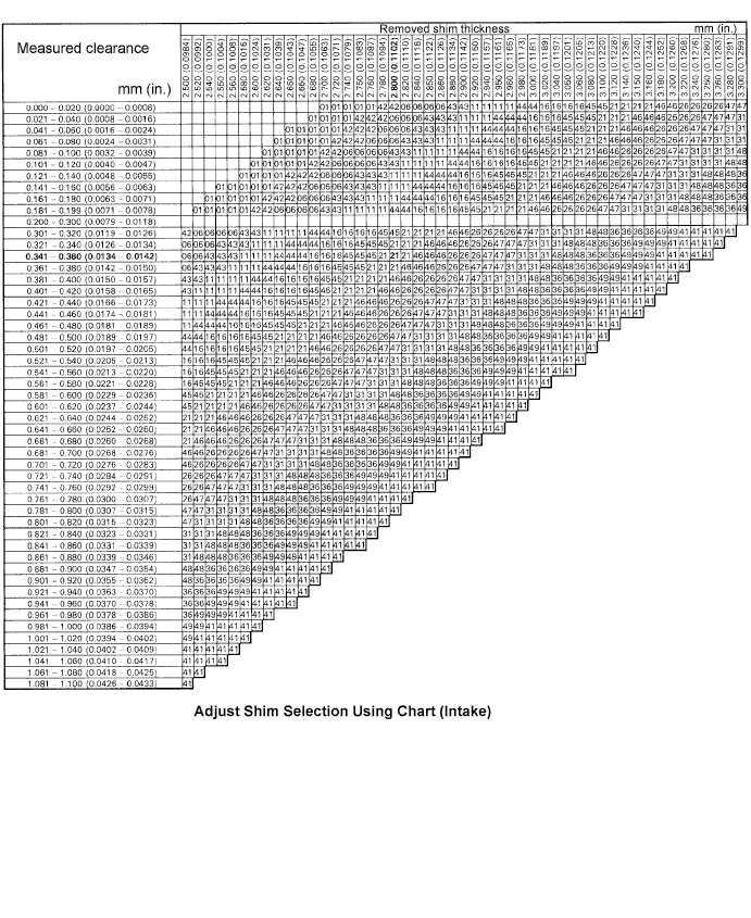
New shim thickness mm (in.) Shim No. Thickness Shim No. Thickness 01 2.50 (0.0984) 46 2.95 (0.1161) 42 2.55 (0.1004) 26 3.00 (0.1181) 06 2.60 (0.1024) 47 3.05 (0.1201) 43 2.65 (0.1043) 31 3.10 (0.1220) 11 2.70 (0.1063) 48 3.15 (0.1240) 44 2.75 (0.1083) 36 3.20 (0.1260) 16 2.80 (0.1102) 49 3.25 (0.1280) 45 2.85 (0.1122) 41 3.30 (0.1299) 21 2.90 (0.1142) Intake valve clearance (Cold) 0.20 to 0.30 mm (0.008 to 0.012 in.) EXAMPLE:
The 2.800 mm (0.1102 in.) shim is installed and the measured clearance is 0.350 mm (0.0138 in.). Replace the 2.800 mm (0.1102 in.) shim with a No.21 shim.
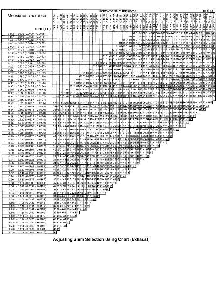
New shim thickness mm (in.) Shim No. Thickness Shim No. Thickness 01 2.50 (0.0984) 46 2.95 (0.1161) 42 2.55 (0.1004) 26 3.00 (0.1181) 06 2.60 (0.1024) 47 3.05 (0.1201) 43 2.65 (0.1043) 31 3.10 (0.1220) 11 2.70 (0.1063) 48 3.15 (0.1240) 44 2.75 (0.1083) 36 3.20 (0.1260) 16 2.80 (0.1102) 49 3.25 (0.1280) 45 2.85 (0.1122) 41 3.30 (0.1299) 21 2.90 (0.1142) Exhaust valve clearance (Cold) 0.40 to 0.50 mm (0.016 to 0.020 in.) EXAMPLE:
The 2.800 mm (0.1102 in.) shim is installed and the measured clearance is 0.350 mm (0.0138 in.). Replace the 2.800 mm (0.1102 in.) shim with a No.11 shim.
-
-
Install a new adjusting shim.
-
Place a new adjusting shim on the valve lifter.
-
Remove the SST.
-
-
Recheck the valve clearance.
-
-
INSTALL CYLINDER HEAD COVER SUB-ASSEMBLY
-
Remove the any oil packing (FIPG) material.
-
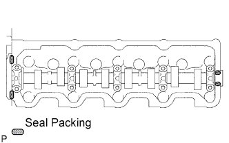
Apply seal packing to the cylinder head as shown in the illustration.
Seal packing Toyota Genuine Seal Packing Black, Three Bond 1207B or equivalent -
Install the gasket to the cylinder head cover.
-
Install the cylinder head cover with the 9 bolts and nut. Uniformly tighten the bolts and nuts in several steps.
- Torque:
- 12 N*m { 120 kgf*cm, 9 ft.*lbf }
-
Connect the ventilation hose.
-
-
INSTALL INTAKE AIR CONNECTOR SUB-ASSEMBLY
-
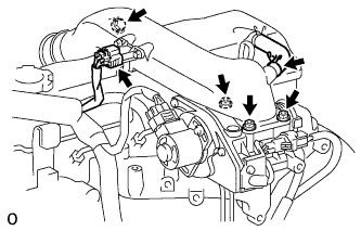
Install a new gasket and intake air connector with the bolt and 3 nuts.
- Torque:
- bolt
- 18 N*m { 184 kgf*cm, 13 ft.*lbf }
- Nut
- 12 N*m { 122 kgf*cm, 9 ft.*lbf }
-
Connect the turbo pressure sensor connector.
-
Connect the ventilation hose.
-
-
CONNECT AIR CLEANER HOSE NO.2
-
Install the air cleaner hose No.2 with the clamp.
-
-
INSTALL TIMING BELT