ДВИГАТЕЛЬ В СБОРЕ СНЯТИЕ

-
PLACE FRONT WHEELS FACING STRAIGHT AHEAD
-
SEPARATE BATTERY NEGATIVE CABLE
-
REMOVE FRONT WHEELS
-
REMOVE ENGINE UNDER COVER NO.1 (w/ Engine Under Cover No.1)
-
REMOVE ENGINE UNDER COVER NO.2 (w/ Engine Under Cover No.2)
-
REMOVE ENGINE SIDE UNDER COVER LH (w/ Engine Side Under Cover LH)
-
REMOVE ENGINE SIDE UNDER COVER RH (w/ Engine Side Under Cover RH)
-
DRAIN POWER STEERING FLUID
-
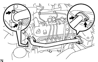
DRAIN ENGINE COOLANT
CAUTION:
Не снимайте пробку расширительного бачка радиатора, пока двигатель и радиатор не остынут. Выброс горячей охлаждающей жидкости и пара под давлением может стать причиной серьезных ожогов.
-
Ослабьте пробку сливного крана радиатора.
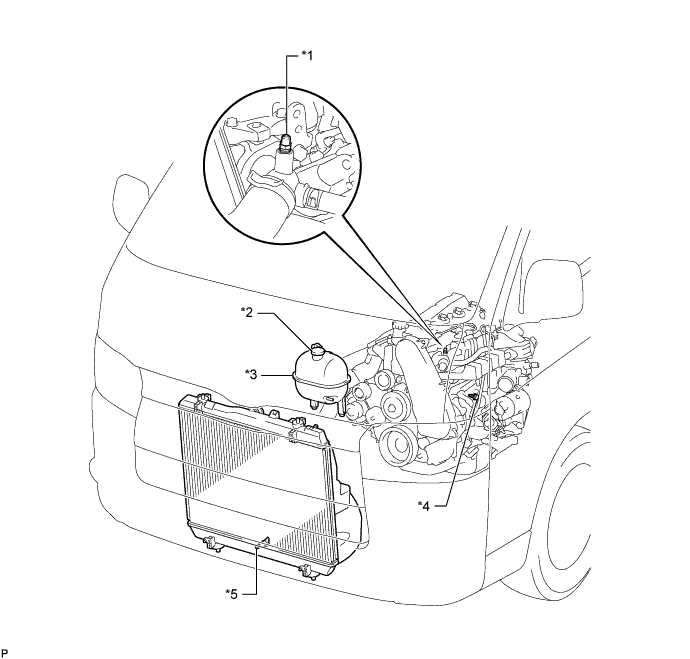
Обозначения на рисунке *1 Прокачной штуцер *2 Пробка расширительного бачка радиатора *3 Расширительный бачок радиатора в сборе *4 Пробка сливного крана блока цилиндров *5 Пробка сливного крана радиатора - - -
Снимите пробку расширительного бачка радиатора.
-
Ослабьте пробку сливного крана блока цилиндров (на крышке масляного радиатора двигателя) и слейте охлаждающую жидкость двигателя.
-
Затяните пробку сливного крана радиатора.
-
Затяните пробку крана сливного отверстия блока цилиндров (на крышке масляного радиатора двигателя).
- Torque:
- 8,0 Н*м { 82 кгс*см, 71 фунт-сила-дюйм }
-
-
DRAIN ENGINE OIL
-
Remove the oil filler cap.
-
Remove the oil drain plug, and drain the engine oil from the oil pan.
-
Install a new gasket and the drain plug.
- Torque:
- 34 N*m { 347 kgf*cm, 25 ft.*lbf }
-
-
REMOVE FRONT SEAT ASSEMBLY RH (for Hi-back Seat Type)
-
Perform the same procedure as above on the opposite side. Click here
-
-
REMOVE FRONT SEAT ASSEMBLY RH (for Low-back Seat Type)
-
Perform the same procedure as above on the opposite side. Click here
-
-
REMOVE FRONT DOOR SCUFF PLATE RH
-
REMOVE ENGINE SERVICE HOLE SUB COVER ASSEMBLY
-
Roll up the carpet, and remove the engine service hole sub cover assembly.
-
-
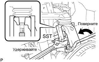
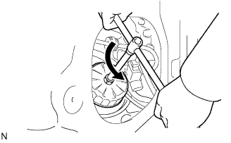
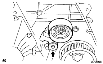
REMOVE FAN & GENERATOR V BELT
-
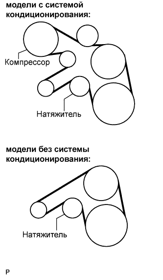
Снимите приводной ремень, повернув шкив натяжителя по часовой стрелке с помощью установочного болта шкива, чтобы ослабить натяжение ремня.
-
-
REMOVE FENDER APRON MUDGUARD SEAL
-
REMOVE AIR CLEANER HOSE ASSEMBLY
-
Remove the bolt and air cleaner hose assembly.
-
-
REMOVE COMPRESSOR OUTLET ELBOW
-
Remove the 2 bolts and 2 clamps, then remove the compressor outlet elbow.
-
-
DISCONNECT OIL RETURN HOSE (w/ Intercooler)
-
Disconnect the oil return hose from the intake manifold.
-
-
DISCONNECT AIR HOSE NO.4
-
Remove the clamp, and disconnect the air hose No.4 from the diesel throttle body.
-
-
DISCONNECT RADIATOR HOSE INLET
-
Remove the clamp, and disconnect the radiator inlet hose from the water inlet.
-
-
DISCONNECT RADIATOR HOSE NO.4
-
Remove the clamp, and disconnect the radiator hose No.4 from the water outlet.
-
-
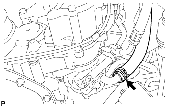
DISCONNECT WATER BY-PASS HOSE NO.3
-
Remove the clamp, and disconnect the water by-pass hose No.3 from the water by-pass pipe.
-
-
DISCONNECT FUEL HOSE NO.2
-
Remove the clamp, and disconnect the fuel hose No.2 from the nozzle leakage pipe No.2.
-
-
DISCONNECT FUEL HOSE NO.1
-
Remove the clamp, and disconnect the fuel hose No.1 from the injection pump assembly.
-
-
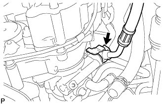
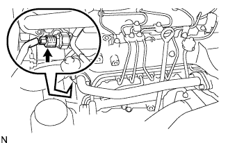
DISCONNECT VACUUM HOSE
-
Disconnect the vacuum hose from the vacuum pump assembly.
-
-
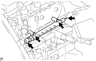
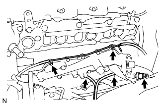
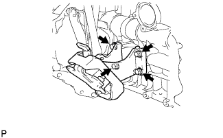
DISCONNECT ENGINE WIRE
-
Disconnect the ECM connector Click here.
-
Disconnect the clamps of the engine wire and earth cable.
-
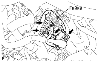
Remove the 4 connectors and nut as shown in the illustration.
-
-
SEPARATE COMPRESSOR AND MAGNETIC CLUTCH (w/ Air Conditioning System)
-
Отсоедините разъем.
-
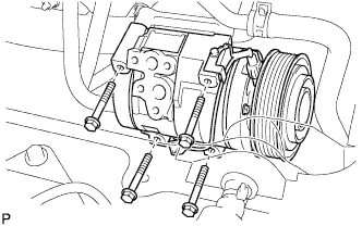
Выверните 4 болта и снимите компрессор и электромагнитную муфту.
-
-
SEPARATE VANE PUMP OIL RESERVOIR ASSEMBLY
-
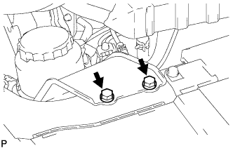
Выверните 2 болта и отсоедините масляный бачок лопастного насоса в сборе.
Note
Подвесьте масляный бачок лопастного насоса в сборе с помощью провода, чтобы не допустить пролива жидкости для механизма рулевого управления с усилителем.
-
-
REMOVE EXHAUST PIPE ASSEMBLY FRONT (for Super Long Wheelbase)
-
Выверните 4 болта, отверните 2 гайки и снимите 2 пружины сжатия. Снимите приемную трубу в сборе и 2 прокладки.
-
Отсоедините опору выпускной трубы и снимите приемную трубу в сборе и 2 прокладки.
-
-
REMOVE EXHAUST PIPE ASSEMBLY FRONT (for Long Wheelbase)
-
Выверните 4 болта, отверните 2 гайки и снимите 2 пружины сжатия. 2 прокладки и приемную трубу в сборе.
-
Отсоедините опору выпускной трубы и снимите приемную трубу в сборе и 2 прокладки.
-
-
REMOVE EXHAUST PIPE ASSEMBLY CENTER (for Super Long Wheelbase)
-
Отверните 2 болта.
-
Отсоедините опоры выпускной трубы и снимите центральную выпускную трубу в сборе и прокладку.
-
-
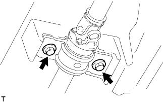
REMOVE PROPELLER WITH CENTER BEARING SHAFT ASSEMBLY (for Super Long Wheelbase)
-
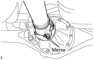
Нанесите метки на оба фланца.
-
Снимите 4 гайки с болтами и шайбами.
Tech Tips
Если фланцевое соединение разделяется с трудом, временно затяните только одну гайку и, равномерно распределяя удары, с помощью молотка и латунного стержня отделите карданный вал с центральным подшипником в сборе от соединительного фланца дифференциала.
-
Выверните 2 болта и снимите центральный опорный подшипник № 1 в сборе.
-
Снимите карданный вал с центральным подшипником в сборе.
-
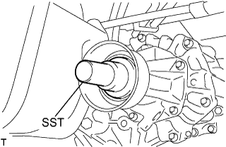
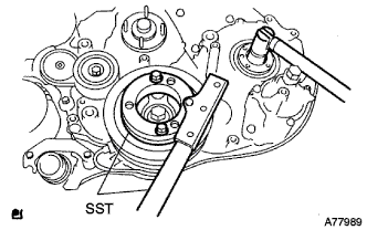
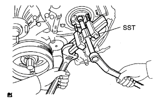
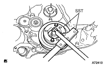
Установите SST в трансмиссию для предотвращения утечки масла.
Note
Будьте осторожны, чтобы не повредить сальник.
-
При работе с автоматической трансмиссией используйте следующий SST.
- SST
- 09325-40010
-
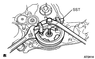
При работе с механической трансмиссией используйте следующий SST.
- SST
- 09325-20010
-
-
-
REMOVE PROPELLER SHAFT ASSEMBLY (for Long Wheelbase)
-
Нанесите метки на оба фланца.
-
Снимите 4 гайки с болтами и шайбами.
Tech Tips
Если фланцевое соединение разделяется с трудом, временно затяните только одну гайку и, равномерно распределяя удары, с помощью молотки и латунного стержня, отделите карданный вал от соединительного фланца дифференциала.
-
Снимите карданный вал в сборе.
-
Установите SST в трансмиссию для предотвращения утечки масла.
Note
Будьте осторожны, чтобы не повредить сальник.
-
При работе с автоматической трансмиссией используйте следующий SST
- SST
- 09325-40010
-
При работе с механической трансмиссией используйте следующий SST
- SST
- 09325-20010
-
-
-
REMOVE SPEED SENSOR FRONT LH (w/ ABS)
-
Выверните 2 болта и отсоедините датчик частоты вращения от поворотного кулака.
Note
-
Будьте осторожны, чтобы не повредить датчик частоты вращения.
-
Не допускайте налипания на датчик частоты вращения посторонних частиц.
-
-
-
REMOVE SPEED SENSOR FRONT RH (w/ ABS)
Tech Tips
Use the same procedures described for the LH side.
-
REMOVE FRONT DISC BRAKE CALIPER ASSEMBLY LH
-
Выверните 2 болта и снимите суппорт тормоза в сборе.
Note
Суппорт тормоза не должен повисать на гибком шланге, поэтому его следует закрепить проводом или каким-либо аналогичным средством.
-
-
REMOVE FRONT DISC BRAKE CALIPER ASSEMBLY RH
Tech Tips
Use the same procedures described for the LH side.
-
SEPARATE FRONT SUSPENSION ARM SUB-ASSEMBLY UPPER LH
-
Снимите шплинт и ослабьте гайку.
- SST
- 09628-62011
Note
Гайку не отворачивайте.
-
Используя SST, отсоедините поворотный кулак от верхнего рычага подвески и отверните гайку.
Note
-
Закрепите поворотный кулак проводом, чтобы к гибкому шлангу не прикладывалось чрезмерное усилие.
-
Не допускайте повреждения пылезащитного чехла шарового шарнира.
-
-
-
SEPARATE FRONT SUSPENSION ARM SUB-ASSEMBLY UPPER RH
Tech Tips
Use the same procedures described for the LH side.
-
SEPARATE SHOCK ABSORBER ASSEMBLY FRONT LH
-
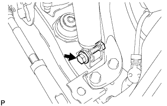
Выверните болт и отсоедините передний амортизатор от нижнего рычага передней подвески.
-
-
SEPARATE SHOCK ABSORBER ASSEMBLY FRONT RH
Tech Tips
Use the same procedures described for the LH side.
-
SEPARATE CLUTCH RELEASE CYLINDER ASSEMBLY (for Manual Transmission)
-
Выверните 2 болта и отсоедините рабочий цилиндр сцепления.
-
-
SEPARATE TRANSMISSION CONTROL CABLE ASSEMBLY (for Manual Transmission)
-
Нанести метки на трос механизма переключения в сборе и наружный рычаг.
-
Отверните 2 гайки и отсоедините трос механизма переключения передач от наружного рычага.
-
С помощью отвертки отцепите захваты 2 фиксаторов.
-
Снимите трос механизма переключения передач и 2 фиксатора с кронштейна троса механизма переключения передач № 1.
-
-
REMOVE TRANSMISSION OIL LEVEL GAUGE SUB-ASSEMBLY (for Automatic Transmission)
-
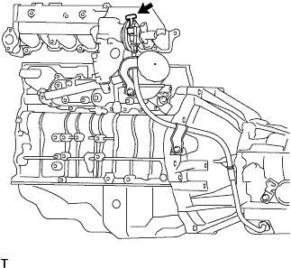
Remove the transmission oil level gauge sub-assembly from the transmission oil filler tube.
-
-
REMOVE TRANSMISSION OIL FILLER TUBE SUB-ASSEMBLY (for Automatic Transmission)
-
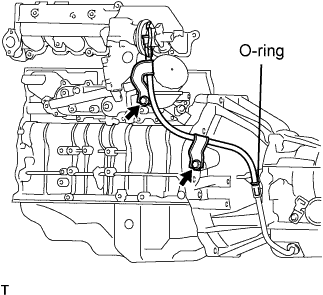
Remove the 2 bolts transmission oil filler tube sub-assembly.
-
Remove the O-ring from the oil filler tube sub-assembly.
-
-
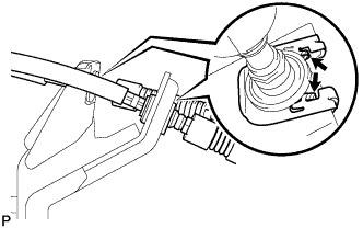
DISCONNECT TRANSMISSION CONTROL CABLE ASSEMBLY (for Automatic Transmission)
-
Remove the nut and disconnect transmission control cable assembly from the transmission control shaft lever assembly.
-
Remove the clip and disconnect the transmission control cable assembly from the transmission control bracket.
-
-
DISCONNECT OIL COOLER TUBE (for Automatic Transmission)
-
Remove each clamp and disconnect the oil cooler inlet tube and oil cooler outlet tube from the oil cooler.
-
-
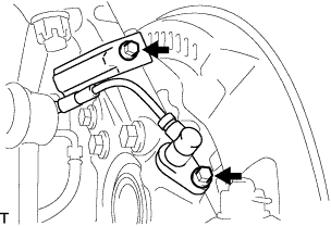
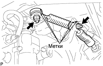
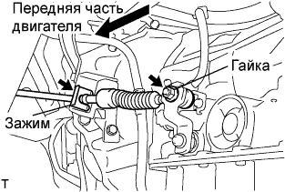
SEPARATE STEERING TORQUE SHAFT ASSEMBLY
-
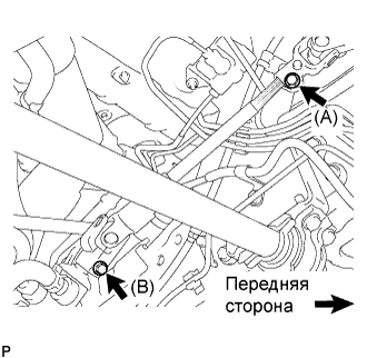
Ослабьте болт (A), выверните болт (B), а затем сдвиньте крутящий вал рулевого управления в сборе.
Tech Tips
-
Не выворачивайте болт (A) полностью.
-
Не отсоединяйте крутящий вал рулевого управления в сборе от тяги рулевого управления с усилителем в сборе.
-
-
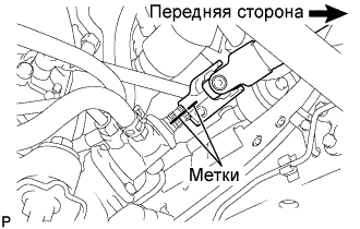
Нанесите метки на крутящий вал рулевого управления в сборе и тягу рулевого управления с усилителем в сборе.
-
Отсоедините крутящий вал рулевого управления в сборе от тяги рулевого управления с усилителем в сборе.
-
-
REMOVE ENGINE ASSEMBLY WITH TRANSMISSION
-
Using the engine lifter, hold the engine assembly and separate the rear engine mount.
-
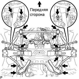
Remove the stabilizer brackets and 16 bolts of the front suspension cross member.
-
Remove the engine assembly w/ transmission out of the vehicle slowly and carefully.
-
-
REMOVE STARTER ASSEMBLY (for 2.0 kW Type)
-
Для моделей с широким кузовом:
Выверните болт и снимите провод соединения с массой.
-
Откройте крышку контакта.
-
Отверните гайку и отсоедините жгут проводов от контакта 30.
-
Отсоедините разъем контакта 50 от стартера в сборе.
-
Выверните болт, отверните 2 гайки и снимите стартер.
-
-
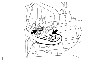
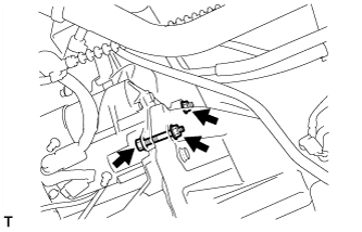
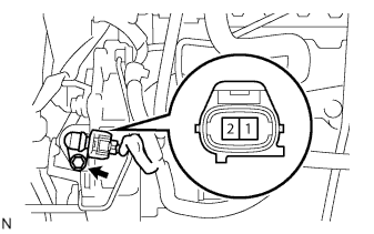
REMOVE STARTER ASSEMBLY (for 2.2 kW Type)
-
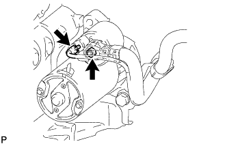
Снимите заглушку контакта № 2.
-
Отсоедините разъем стартера.
-
Отверните гайку и отсоедините провод стартера.
-
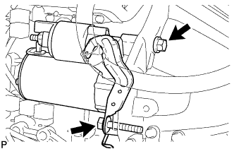
Выверните 2 болта и отсоедините кронштейн зажима жгута проводов.
-
Снимите стартер в сборе.
-
-
REMOVE STARTER ASSEMBLY (for 2.7 kW Type)
-
Для моделей с широким кузовом:
Выверните болт и отсоедините провод соединения с массой.
-
Откройте крышку контакта.
-
Отверните гайку и отсоедините жгут проводов от контакта 30.
-
Отсоедините разъем контакта 50 от стартера в сборе.
-
Выверните болт, отверните 2 гайки и снимите стартер.
-
-
REMOVE MANUAL TRANSMISSION UNIT ASSEMBLY (for Manual Transmission)
-
REMOVE AUTOMATIC TRANSMISSION ASSEMBLY (for Automatic Transmission)
-
REMOVE CLUTCH COVER ASSEMBLY (for Manual Transmission)
-
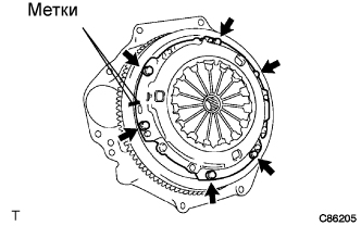
Put matchmarks on the clutch cover assembly and the flywheel sub-assembly.
-
Loosen each set bolt one turn at a time until spring tension is released.
-
Remove the set bolts, and pull off the clutch cover assembly.
Note
Do not drop the clutch disc assembly.
-
-
REMOVE CLUTCH DISC ASSEMBLY (for Manual Transmission)
Note
Keep the lining part of the clutch disc assembly, the pressure plate and surface of the flywheel sub-assembly away from oil and foreign matter.
-
REMOVE FLYWHEEL SUB-ASSEMBLY
-
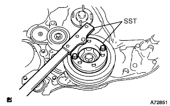
Fix the crankshaft with SST.
- SST
- 09213-58013
- 09330-00021
-
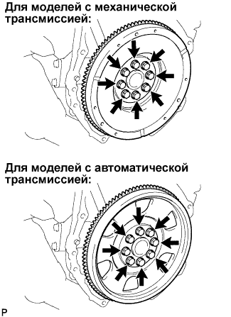
For manual transmission.
-
Remove the 8 bolts and flywheel.
-
-
For automatic transmission.
-
Remove the 8 bolts, and remove the drive plate spacer rear, drive plate and flywheel.
-
-
-
REMOVE REAR END PLATE
-
Remove the bolt and rear end plate.
-
-
REMOVE ENGINE WIRE
-
Disconnect the engine wire from the engine assembly.
-
-
INSTALL ENGINE HANGERS
-
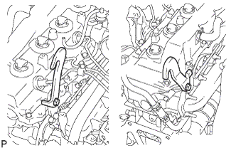
Set the engine hanger No.1 upper and engine hanger No.2 to the locations shown in the illustration.
- Torque:
- Engine hanger No.1 upper
- 25 N*m { 255 kgf*cm, 18 ft.*lbf }
- Engine hanger No.2
- 68 N*m { 693 kgf*cm, 50 ft.*lbf }
Parts name Parts No. Engine hanger No.1 upper
Bolt
12284-30020
91512-61014
Engine hanger No.2
Bolt
12282-67020
91642-81030
Note
Use a new bolt for the engine hanger.
-
-
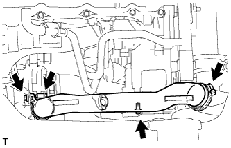
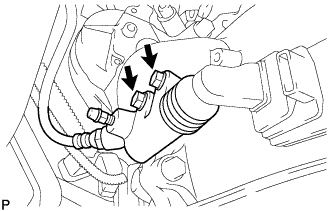
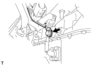
SEPARATE OIL RESERVOIR TO PUMP HOSE NO.1
-
Снимите хомут и отсоедините шланг № 1 соединения масляного бачка с насосом.
-
-
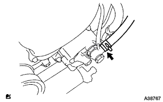
SEPARATE PRESSURE FEED TUBE ASSEMBLY
-
Выверните пустотелый соединительный болт-штуцер и отсоедините нагнетательный патрубок в сборе.
-
-
REMOVE FRONT SUSPENSION CROSS MEMBER
-
Hold the engine with the engine sling device and chain block.
-
Remove the 4 bolts from the front suspension cross member.
-
Remove the engine assembly by operating the engine sling device and chain block.
-
-
INSTALL ENGINE STAND
-
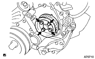
REMOVE VANE PUMP ASSEMBLY
-

Отверните 2 гайки и снимите лопастной насос в сборе.
-
Снимите кольцевое уплотнение лопастного насоса с лопастного насоса в сборе.
-
-
REMOVE TIMING BELT COVER NO.1
-
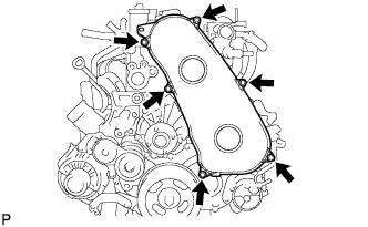
Remove the 6 bolts and timing belt No.1 cover.
-
-
REMOVE TIMING BELT
-
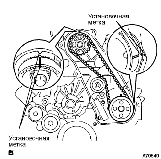
Turn the crankshaft in the clockwise direction and align the timing marks as shown in the illustration.
-
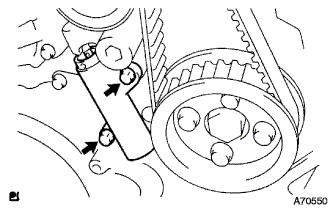
Uniformly loosen the 2 bolts, and remove the chain tensioner assembly No.1.
-
Remove the timing belt.
-
-
REMOVE FAN PULLEY
-
Remove the 4 nuts and fan pulley.
-
-
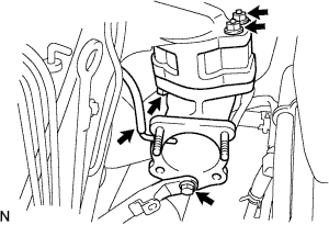
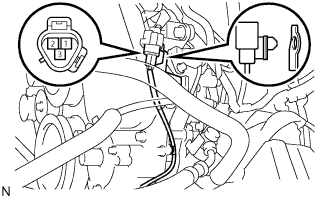
REMOVE EGR PIPE SUB-ASSEMBLY NO.1 (w/ EGR Valve)
-
Отсоедините разъем датчика давления в топливной системе.
-
Выверните 2 болта, отверните 2 гайки и снимите трубу РОГ.
-
Снимите 2 прокладки.
-
-
REMOVE DIESEL THROTTLE BODY ASSEMBLY
-
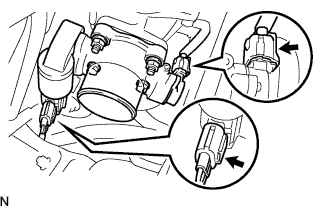
Отсоедините 2 разъема корпуса дроссельной заслонки.
-
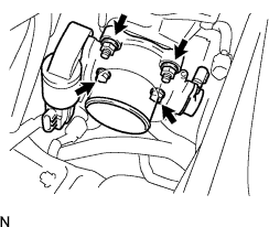
Выверните 2 болта, отверните 2 гайки и снимите корпус дроссельной заслонки дизельного двигателя в сборе.
-
Снимите прокладку с патрубка подачи воздуха.
-
-
REMOVE INTAKE AIR CONNECTOR (w/o EGR Valve)
-
Remove the bolt, and separate the manifold stay.
-
Disconnect the vacuum hose from intake air connector.
-
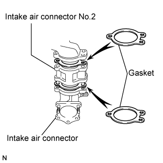
Remove the bolt, 2 nuts and the intake air connector assembly.
-
Remove the 2 gaskets and intake air connector No.2 from the intake air connector.
-
-
REMOVE ELECTRIC EGR CONTROL VALVE ASSEMBLY (w/ EGR Valve)
-
Remove the vacuum regulating valve.
-
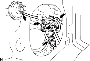
Remove the 2 vacuum hoses and the vacuum regulating valve connector.
-
Remove the 2 bolts and the vacuum regulating valve.
-
-
Remove the EGR valve assembly with the sensor.
-
Remove the bolt, and separate the manifold stay.
-
Disconnect the vacuum hose from the intake air connector.
-
Disconnect the intake air temperature sensor connector.
-
Disconnect the EGR valve position sensor connector.
-
Remove the bolt, 2 nuts and the intake air connector assembly.
-
Remove the 2 gaskets and EGR valve assembly from the intake air connector.
-
-
-
REMOVE OIL LEVEL GAUGE GUIDE
-
Remove the oil level gauge.
-
Remove the bolt and oil level gauge guide.
-
-
REMOVE INJECTION PIPE
- SST
- 09023-12701
-
Remove the injection pipe.
-
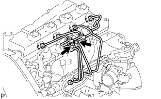
Remove the 2 nuts and injection pipe clamp No.3.
-
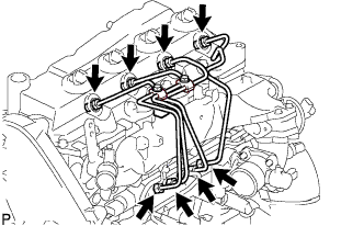
Using SST, remove the 4 injection pipes.
- SST
- 09023-12701
-
-
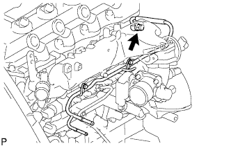
REMOVE FUEL INLET PIPE SUB-ASSEMBLY
-
Using SST, remove the fuel inlet pipe sub-assembly.
- SST
- 09023-12701
-
-
REMOVE NOZZLE LEAKAGE PIPE ASSEMBLY NO.2
-
Remove the union bolt and gasket.
-
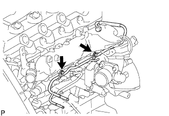
Remove the 2 bolts and the nozzle leakage pipe assembly No.2.
-
-
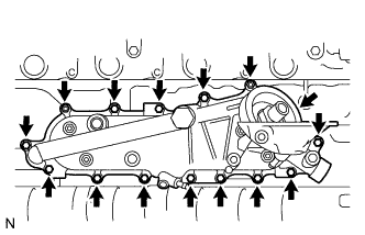
REMOVE INTAKE MANIFOLD
-
Remove the bolt, nut, and the manifold stay.
-
Remove the bolt, and disconnect the ground cable.
-
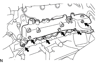
Remove the 4 bolts, 2 nuts, and intake manifold.
-
Remove the gasket from the cylinder head.
-
-
REMOVE OIL FILTER SUB-ASSEMBLY
-
Using SST, remove the oil filter.
- SST
- 09228-07501
Tech Tips
Position the drain oil container to collect the oil from the oil filter.
-
-
REMOVE COMMON RAIL ASSEMBLY
-
Disconnect the fuel pressure sensor connector from the common rail assembly.
-
Disconnect the fuel hose from the fuel pressure limiter.
-
Remove the 2 bolts and common rail assembly.
-
-
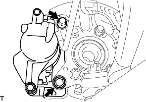
REMOVE INJECTION OR SUPPLY PUMP ASSEMBLY
-
Remove the 4 bolts.
-
Remove the camshaft timing pulley flange No.2 and pump drive shaft pulley.
-
Using SST, remove the supply pump gear set nut and O-ring while holding the crankshaft pulley.
- SST
- 09213-58013
- 09330-00021
-
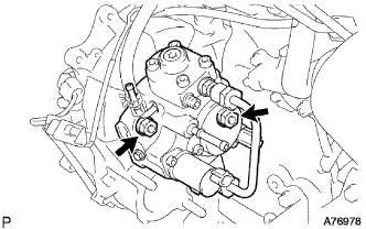
Disconnect the 2 fuel hoses.
-
Disconnect the 2 connectors and wire harness.
-
Loosen the 2 nuts as shown in the illustration.
-
Using SST, disengage the supply pump from the supply pump gear.
- SST
- 09950-50013 ( 09951-05010, 09952-05010, 09953-05020, 09954-05021 )
-
Remove the 2 nuts and supply pump from the engine.
-
Remove the O-ring from the supply pump.
-
Remove the pulley key from the supply pump.
-
-
REMOVE OIL COOLER COVER SUB-ASSEMBLY (w/o EGR Valve)
-
Disconnect the oil pressure switch connector.
-
Disconnect the oil filter drain hoses.
-
Remove the 2 nuts, 13 bolts, oil cooler cover, and gasket.
-
-
REMOVE OIL COOLER COVER SUB-ASSEMBLY (w/ EGR Valve)
-
Disconnect the oil pressure switch connector.
-
Disconnect the oil filter drain hoses.
-
Remove the 2 nuts and the vacuum transmitting pipe No.2 from the oil cooler cover.
-
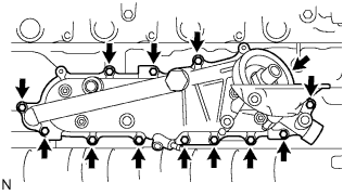
Remove the 13 bolts, oil cooler cover, and gasket.
-
-
REMOVE WATER OUTLET
-
Remove the 2 bolts, water outlet and gasket.
-
-
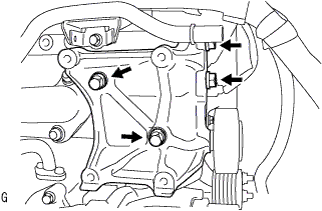
REMOVE ENGINE MOUNTING BRACKET FRONT NO.1 LH
-
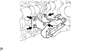
Remove the 4 bolts and the engine mounting bracket front No.1 LH.
-
-
REMOVE GLOW PLUG NO.1 CONNECTOR
-
Remove the 4 grommets.
-
Remove the 4 nuts and glow plug No.1 connectors.
-
-
REMOVE GLOW PLUG
-
Using a deep socket wrench (12 mm), remove the 4 glow plugs.
-
-
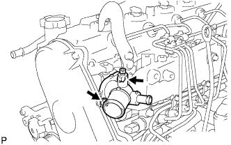
REMOVE WATER INLET
-
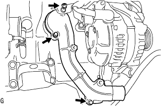
Remove the 3 bolts and water inlet.
-
-
REMOVE THERMOSTAT
-
Remove thermostat and gasket.
-
-
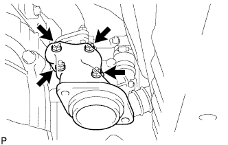
REMOVE COMPRESSOR BRACKET (w/ Air Conditioning System)
-
Remove the 4 bolts and compressor bracket.
-
-
REMOVE IDLE PULLEY ASSEMBLY (w/ Air Conditioning System)
-
Remove the bolt, washers and idle pulley assembly.
-
-
REMOVE GENERATOR BRACKET
-
Remove the 2 bolts and generator bracket.
-
-
REMOVE GENERATOR ASSEMBLY
-
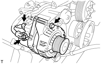
Disconnect the generator connector.
-
Remove the terminal cap.
-
Remove the nut and disconnect the wire harness from terminal B.
-
Remove the bolt and generator assembly.
-
-
REMOVE V-RIBBED BELT TENSIONER ASSEMBLY
-
Remove the 4 bolts and belt tensioner assembly.
-
-
REMOVE VENTILATION PIPE
-
Remove the bolt and ventilation pipe.
-
-
REMOVE VENTILATION HOSE HEAT INSULATOR
-
Remove the 2 bolts and ventilation hose insulator heat.
-
-
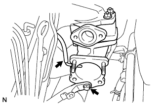
REMOVE TURBINE OUTLET ELBOW
-
Remove the 4 nuts and the turbine outlet elbow.
-
-
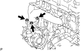
REMOVE TURBOCHARGER STAY
-
Remove the 3 bolts and the turbocharger stay.
-
-
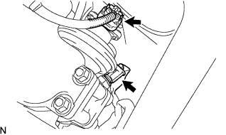
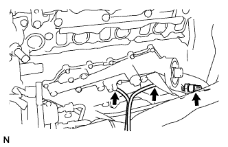
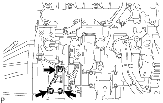
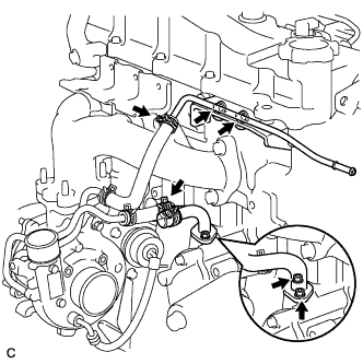
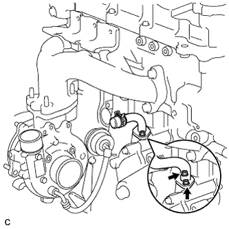
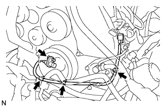
REMOVE TURBO OIL INLET PIPE SUB-ASSEMBLY
-
Remove the 2 bolts and the turbo oil inlet pipe from the cylinder block. (A)
Tech Tips
Place a container under the connection before disconnecting the turbo oil inlet pipe because oil in the pipe may spill out.
-
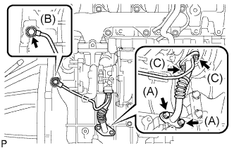
Remove the 2 bolts and the turbo oil inlet pipe from the turbocharger. (C)
-
Remove the union-bolt and gasket from the turbo oil inlet pipe. (B)
-
Remove the 2 gaskets.
-
-
REMOVE COMPRESSOR ELBOW STAY
-
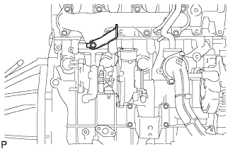
Remove the bolt and the compressor elbow stay.
-
-
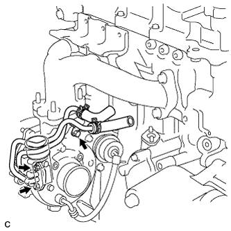
REMOVE WATER BY-PASS PIPE SUB-ASSEMBLY NO.2
-
Water cooled turbocharger (w/ heater)
-
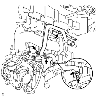
Disconnect the clip and the heater water inlet hose E.
-
Disconnect the clip and the water by-pass hose No.3.
-
Disconnect the 2 clips and the 2 water hoses.
-
Remove the 2 nuts, bolts and water bypass pipe No.2.
-
Remove the gasket.
-
-
Water cooled turbocharger (w/o heater)
-
Disconnect the clip and the water by-pass hose No.3.
-
Disconnect the 2 clips and the 2 water hoses.
-
Remove the 2 bolts and the turbo water pipe No.2.
-
Remove the 2 nuts and water by-pass pipe No.2.
-
Remove the gasket.
-
-
Air cooled turbocharger (w/o heater)
-
Remove the 2 nuts and water by-pass pipe No.2.
-
Remove the gasket.
-
-
-
REMOVE TURBO WATER PIPE SUB-ASSEMBLY NO.2 (for Water Cooled Turbocharger)
-
Remove the bolt, 2 nuts and the turbo water pipe.
-
-
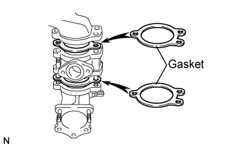
REMOVE TURBOCHARGER SUB-ASSEMBLY
-
Remove the 3 bolts and the turbocharger.
-
Remove the gasket.
-
-
REMOVE EXHAUST MANIFOLD
-
Remove the 2 bolts, 6 nuts and the exhaust manifold from the cylinder head.
-
-
REMOVE ENGINE MOUNTING BRACKET FRONT NO.1 RH
-
Remove the 4 bolts and the engine mounting bracket front No.1 RH.
-
-
REMOVE TIMING BELT IDLER SUB-ASSEMBLY NO.1
-
Using a 10 mm socket hexagonal wrench, remove the bolt, plate washer and timing belt idler No.1.
-
-
REMOVE CRANKSHAFT PULLEY
-
Remove the bolt holding the crankshaft with SST.
- SST
- 09213-58013
- 09330-00021
-
Insert the service bolt.
-
Remove the crankshaft pulley with SST.
- SST
- 09950-50013 ( 09951-05010, 09952-05010, 09953-05020, 09954-05021 )
-
-
REMOVE VACUUM PUMP ASSEMBLY
-
REMOVE DIESEL ENGINE WATER TEMPERATURE SENSOR
-
Using a deep-socket wrench (17 mm), remove the water temperature sensor.
-
-
REMOVE CAMSHAFT POSITION SENSOR
-
Disconnect the camshaft position sensor connector.
-
Remove the bolt and the camshaft position sensor.
-
-
REMOVE CRANKSHAFT POSITION SENSOR
-
Disconnect the crankshaft position sensor connector.
-
Separate the connector from the vacuum pipe No.1.
-
Separate the 3 wire harness clamps.
-
Remove the bolt and the crankshaft position sensor.
-
-
REMOVE ENGINE OIL LEVEL SENSOR
-
Remove the 4 bolts and engine oil level sensor.
-
-
REPLACE PARTIAL ENGINE ASSEMBLY