РАСПРЕДВАЛ УСТАНОВКА

-
INSTALL CAMSHAFT
-
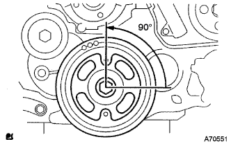
Set the crankshaft to 90° position from the TDC/compression.
-
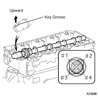
Place the camshaft to the cylinder head as shown in the illustration.
Note
Apply engine oil to the cams, thrusts and gears of the camshaft as well as on the journal of the cylinder head.
-
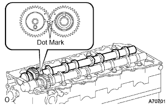
Align the dot marks of the camshaft and No.2 camshaft by meshing the both gears before placing the No.2 camshaft.
-
Remove old packing (FIPG) from the camshaft bearing cap.
-
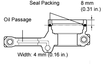
Apply seal packing to the specific places shown in the illustration.
Seal packing Toyota Genuine Seal Packing Black, Three Bond 1207B or equivalent Thickness 1 mm (0.04 in.) Note
-
Be careful not to adhere FIPG to the oil passage of the bearing cap.
-
After applying FIPG, install the camshaft bearing cap within 3 minutes and then tighten its bolts within 15 minutes.
-
Do not start the engine 2 hours after the installation.
-
-
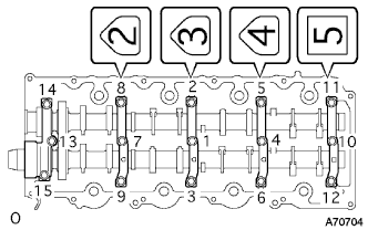
Install the camshaft bearing cap as shown in the illustration.
-
Tighten the 15 bolts for the camshaft bearing cap in the specified order shown in the illustration.
- Torque:
- 19 N*m { 194 kgf*cm, 14 ft.*lbf }
-
Adjust and inspect valve clearance.
-
Fix the timing belt cover No.2 with the 4 bolts and nuts.
- Torque:
- 10 N*m { 102 kgf*cm, 7 ft.*lbf }
-
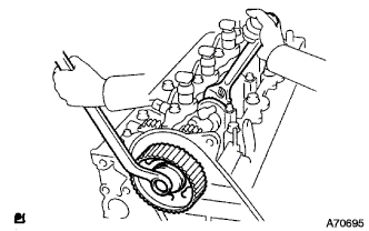
Tighten the bolt for the camshaft timing pulley while holding the camshaft with a monkey wrench.
- Torque:
- 98 N*m { 1,000 kgf*cm, 72 ft.*lbf }
-
Adjust and inspect the valve clearance. Click here
-
Remove the camshaft timing pulley and timing belt cover No.2.
-
-
-
INSTALL CAMSHAFT SETTING OIL SEAL
-
Apply a bit of MP grease to a new oil seal's lip.
Note
Keep the lip clean. Do not to bring dirt and dust on that area.
-
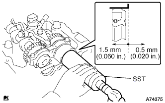
Using SST and a hammer, fit the oil seal.
- SST
- 09608-06041
Oil seal depth from flat end face 0.5 to 1.5 mm (0.020 to 0.060 in.) Note
Install the oil seal straight.
-
-
INSTALL INJECTOR ASSEMBLY
-
CHECK NOZZLE LEAKAGE PIPE LEAK
-
INSTALL TIMING BELT COVER NO.2
-
Remove old seal packing (FIPG) from the timing gear case.
-
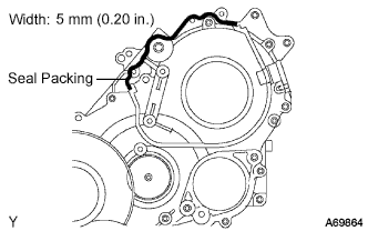
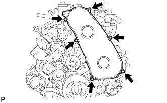
Apply seal packing to the specific places shown in the illustration.
Seal packing Toyota Genuine Seal Packing Black, Three Bond 1207B or equivalent Note
-
After applying FIPG, install the timing belt No.2 cover within 3 minutes and tighten its bolts and nuts within 15 minutes.
-
Do not start the engine 2 hours after the installation.
-
-
Fix the timing belt cover No.2 with the 4 bolts and nuts.
- Torque:
- 10 N*m { 102 kgf*cm, 7 ft.*lbf }
-
-
INSTALL TIMING BELT IDLER SUB-ASSEMBLY NO.1
-
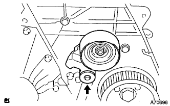
Using a 10 mm socket hexagon wrench, install the new plate washer and timing belt idler No.1.
- Torque:
- 35 N*m { 357 kgf*cm, 26 ft.*lbf }
-
-
INSTALL CAMSHAFT TIMING PULLEY
-
Install the camshaft timing pulley.
-
Tighten the bolt for the camshaft timing pulley while holding the camshaft with a monkey wrench.
- Torque:
- 98 N*m { 1,000 kgf*cm, 72 ft.*lbf }
-
-
PISTON AND VALVE BREAK PREVENT WORK
-
При повороте распредвала со снятым приводным ремнем газораспределения поверните коленчатый вал на 90° против часовой стрелки.
Note
При установке приводного ремня газораспределения поверните распредвал, чтобы совместить синхронизирующие метки, а затем поверните коленчатый вал по часовой стрелке и совместите синхронизирующие метки, как показано на рисунке.
-
-
INSTALL TIMING BELT
-
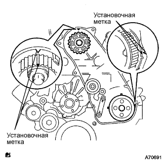
Удостоверьтесь, что установочные метки совмещены, как показано на рисунке.
-
Установите приводной ремень газораспределения на шкив приводного вала насоса, зубчатое колесо распредвала и опорный ролик приводного ремня газораспределения № 1, придерживаясь этой последовательности.
-

Установите натяжитель вертикально на пресс.
Note
-
Не допускайте царапания и деформирования конца толкателя.
-
Запрессуйте толкатель натяжителя.
-
Обеспечьте защиту конца толкателя от повреждений ветошью.
-
-
С помощью пресса медленно запрессуйте толкатель с усилием 981 - 9807 Н (100 - 1000 кгс, 220 - 2205 фунт-силы).
Note
Не прикладывайте к толкателю усилие свыше 981 - 9807 Н (100 - 1000 кгс, 220 - 2205 фунт-силы).
-
Совместите отверстия в толкателе и кожухе. Для сохранения положения установки толкателя пропустите через отверстия шестигранную головку на 1,27 мм.
-
Временно закрепите натяжитель приводного ремня 2 болтами, прижимая опорный ролик к приводному ремню газораспределения.
-
Затяните 2 болта.
- Torque:
- 13 Н*м { 133 кгс*см, 10 фунт-сила-футов }
Note
Равномерно затяните 2 болта и установите натяжитель
-
Выньте из натяжителя торцевой гаечный ключ на 1,5 мм.
-
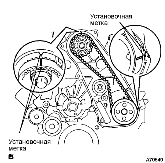
Поверните коленчатый вал по часовой стрелке на два оборота и убедитесь, что установочные метки совмещены, как показано на рисунке.
-
-
INSTALL TIMING BELT COVER NO.1
-
Установите крышку приводного ремня газораспределения № 1 и закрепите ее 6 болтами.
- Torque:
- 6,0 Н*м { 61 кгс*см, 53 фунт-сила-дюйма }
-
Присоедините зажим жгута проводов.
-
-
INSTALL CYLINDER HEAD COVER SUB-ASSEMBLY
-
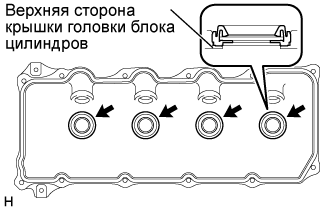
Install 4 new No. 3 cylinder head cover gaskets to the cylinder head cover as shown in the illustration.
Note
-
Do not install the gaskets at an angle.
-
Keep the lip of the gasket free from foreign materials.
-
-
Install a new cylinder head cover gasket to the cylinder head cover.
-
Remove old seal packing (FIPG) from the cylinder head.
-
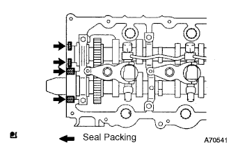
Apply a seal packing to the specific places described in the illustration.
Seal packing Toyota Genuine Seal Packing Black, Three Bond 1207B or equivalent Note
-
After applying the seal packing, parts must be assembled within 3 minutes, and then tighten within 15 minutes.
-
Otherwise the material must be removed and reapplied.
-
Do not start the engine 2 hour after the installation.
-
-
Install the cylinder head cover with 10 bolts and 2 nuts.
- Torque:
- 9.0 N*m { 92 kgf*cm, 80 in.*lbf }
-
Connect the ventilation hose.
-
Install a new nozzle holder seal.
-
-
INSTALL INJECTION PIPE
- SST
- 09023-12701
Note
-
When replacing the fuel injector, common rail, or cylinder head with a new one, replace injection pipes No. 1, No. 2, No. 3, and No. 4.
-
Keep clean the joint of the injection pipe.
-
Install the injection pipes.
-
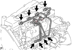
Temporarily install the 4 injection pipes.
-
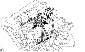
Install the injection pipe clamp No.3 in 2 nuts.
- Torque:
- 5.0 N*m { 51 kgf*cm, 44 in.*lbf }
-
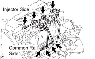
Fasten the union sequentially, from the injection pipe common rail to the injector, using SST.
- SST
- 09023-12701
- Torque:
- Use union nut wrench and torque wrench
- 32 N*m { 326 kgf*cm, 24 ft.*lbf }
-
-
INSTALL VANE PUMP OIL RESERVOIR ASSEMBLY
-
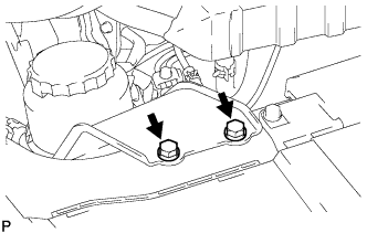
Установите масляный бачок лопастного насоса в сборе и закрепите 2 болтами.
- Torque:
- 8,0 Н*м { 82 кгс*см, 71 фунт-сила-дюйм }
-
-
INSTALL FAN & GENERATOR V BELT
-
Провернув шкив натяжителя поликлинового ремня по часовой стрелке, установите поликлиновой ремень вентилятора и генератора.
Note
Проверьте правильность посадки поликлинового ремня вентилятора и генератора на каждом шкиве.
-
Проверьте метку индикатора натяжителя поликлинового ремня (см. стр. Click here).
-
-
INSTALL ENGINE SERVICE HOLE SUB COVER SUB-ASSEMBLY
-
Установите вспомогательную крышку технологического отверстия двигателя и закрепите ее 5 болтами.
- Torque:
- 13 Н*м { 133 кгс*см, 10 фунт-сила-футов }
-
-
INSTALL FRONT DOOR SCUFF PLATE RH
-
INSTALL FRONT SEAT ASSEMBLY RH (for Hi-back Seat Type)
-
Perform the same procedure as above on the opposite side. Click here
-
-
INSTALL FRONT SEAT ASSEMBLY RH (for Low-back Seat Type)
-
Perform the same procedure as above on the opposite side. Click here
-
-
CONNECT BATTERY NEGATIVE TERMINAL
-
ADD ENGINE COOLANT
-
Надежно затяните сливные пробки.
-
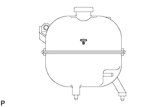
Залейте охлаждающую жидкость в расширительный бачок системы охлаждения до верха горловины.
Номинальный объем Параметр / Устройство Заданные условия Для моделей без подогревателя 13,6 литра (14,4 кварты США, 12,0 английской кварты) Для моделей с передним подогревателем 14,6 литра (15,4 кварты США, 12,8 английской кварты) Для моделей с передним и задним подогревателями 16,6 литра (17,5 кварты США, 14,6 английской кварты) Note
Не доливайте простую воду вместо охлаждающей жидкости двигателя.
Tech Tips
-
Использование неподходящей охлаждающей жидкости может привести к повреждению системы охлаждения двигателя.
-
Разрешается использовать только охлаждающую жидкость "TOYOTA Super Long Life Coolant" или аналогичную высококачественную охлаждающую жидкость на основе этиленгликоля (а не на силикатной, аминовой, нитритной или борнокислой основе), изготовленную по гибридной технологии органических кислот с длительным сроком годности (охлаждающая жидкость, изготовленная по гибридной технологии органических кислот, состоит из низкофосфатных соединений и органических кислот).
-
-
Ослабьте прокачной штуцер корпуса отводящего патрубка.
-
После удаления воздуха и слива охлаждающей жидкости надежно затяните прокачной штуцер.
- Torque:
- 8,0 Н*м { 82 кгс*см, 71 фунт-сила-дюйм }
-
Долейте охлаждающую жидкость в расширительный бачок радиатора до отметки B и установите пробку радиатора.
-
Прогревайте двигатель, пока не откроется термостат.
-
Когда термостат откроется, несколько минут прокачивайте охлаждающую жидкость.
Tech Tips
Время открывания термостата можно проверить, сжав входной патрубок радиатора рукой и убедившись, что охлаждающая жидкость поступает в шланг.
-
-
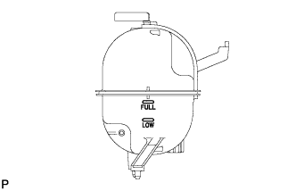
После охлаждения двигателя убедитесь, что уровень охлаждающей жидкости находится между отметками "LOW" и "FULL".
-
-
BLEED FUEL LINE
-
Push the priming pump for several times to fill up the fuel lines with fuel.
-
-
CHECK FUEL LEAK
-
PERFORM ACTIVE TEST
-
Connect the intelligent tester to the DLC3.
-
Turn the ignition switch on.
-
Turn the intelligent tester on.
-
Enter the following menus: Powertrain / ECD / Active Test.
-
Perform the Active Test.
Intelligent Tester Display Test Details Control Range Diagnostic Notes Test the Fuel Leak Pressurizes common rail internal fuel pressure, and checks for fuel leaks Stop/Start
-
Fuel pressure inside common rail pressurized to specified value and engine speed increased to 2,000 rpm when ON is selected
-
Above conditions preserved while test is ON
-
-
-
-
CHECK FOR ENGINE OIL LEAKS
-
CHECK FOR ENGINE COOLANT LEAKS
CAUTION:
Не снимайте пробку радиатора, пока двигатель и радиатор не остынут. Выброс горячей охлаждающей жидкости и пара под давлением может стать причиной серьезных ожогов.
-
Заполните радиатор охлаждающей жидкостью и подсоедините к радиатору приспособление для опрессовки системы охлаждения и проверки пробки радиатора.
-
Прогрейте двигатель.
-
С помощью приспособления для опрессовки системы охлаждения и проверки пробки радиатора увеличьте давление в радиаторе до 137 кПа (1,4 кгс/см2, 19,9 фунтов на кв. дюйм) и убедитесь, что давление не падает.
Tech Tips
Если давление снижается, проверьте на наличие утечек шланги, радиатор и насос системы охлаждения. При отсутствии внешних утечек проверьте сердцевину отопителя, блок цилиндров и головку блока цилиндров.
-
-
INSTALL ENGINE UNDER COVER NO.1 (w/ Engine Under Cover No.1)
- Torque:
- 13 N*m { 133 kgf*cm, 10 ft.*lbf }
-
CHECK IDLE SPEED
Note
This checking procedure should be done under the following condition.
Tech Tips
-
Regarding the details about the intelligent tester, refer to its operator's manual.
-
If the intelligent tester is not available, a tachometer's tester probe can substitute for it.
-
Connect the intelligent tester to the DLC3.
-
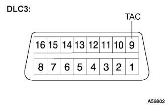
If the tester is not available, connect a tester probe of a tachometer to terminal 9 (TAC) of the DLC3 with SST.
- SST
- 09843-18030
-
Start the engine and check the idle speed.
Idle speed 700 to 800 rpm Tech Tips
If the idle speed is not as specified, check by troubleshooting in the diagnostics section.
-
In case of the tester probe of the tachometer is connected to the DLC3, disconnect the tester probe from terminal 9 of the DLC3 with SST.
-
Disconnect the intelligent tester from the DLC3.
-
-
INSPECT MAXIMUM ENGINE SPEED
Note
This checking procedure should be done under the following condition.
Tech Tips
-
Regarding the details about the intelligent tester, refer to its operator's manual.
-
If the intelligent tester is not available, a tachometer's tester probe can substitute for it.
-
Connect the intelligent tester to the DLC3.
-
If the tester is not available, connect a tester probe of a tachometer to terminal 9 (TAC) of the DLC3 with SST.
- SST
- 09843-18030
-
Start the engine.
-
Depress the accelerator pedal all the way to the limit.
-
Check the maximum speed.
Maximum speed 4500 to 4700 rpm Tech Tips
If the maximum speed is not as specified, check by troubleshooting in the diagnostics section.
-
In case of the tester probe of the tachometer is connected to the DLC3, disconnect the tester probe from terminal 9 of the DLC3 with SST.
-
Disconnect the intelligent tester from the DLC3.
-
-
PERFORM INITIALIZATION