ДВИГАТЕЛЬ В СБОРЕ УСТАНОВКА

-
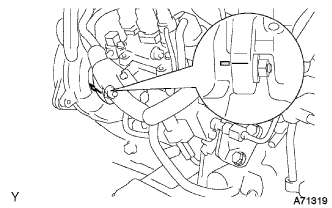
INSTALL WIRE HARNESS CLAMP BRACKET
-
Install the bolt and wire harness clamp bracket.
-
-
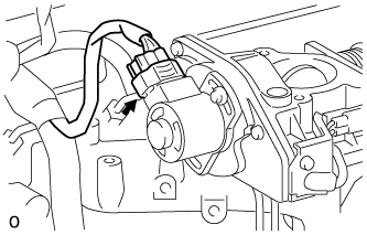
INSTALL ENGINE OIL PRESSURE SWITCH ASSEMBLY
-
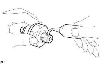
Clean the threads of the oil pressure switch, and apply adhesive to them.
Adhesive Toyota Genuine Adhesive 1344, Three Bond 1344 or equivalent -
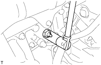
Using a 24 mm deep socket wrench, install the oil pressure switch.
- Torque:
- 15 N*m { 155 kgf*cm, 11 ft.*lbf }
-
-
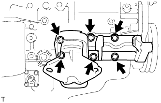
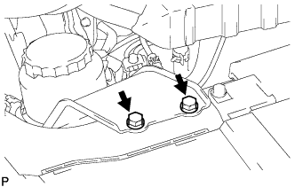
INSTALL OIL FILTER BRACKET SUB-ASSEMBLY
-
Install a new gasket and oil filter bracket with the 10 bolts and 2 nuts.
- Torque:
- 30 N*m { 300 kgf*cm, 22 ft.*lbf }
-
-
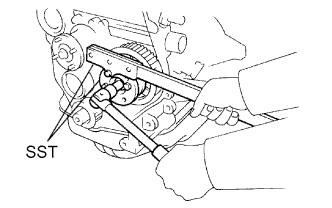
INSTALL OIL FILTER SUB-ASSEMBLY
-
Check and clean the oil filter installation surface.
-
Apply clean engine oil to the rubber gasket of a new oil filter.
-
Instal the oil filter, and tighten it by hand until the rubber gasket contacts the installation surface.
-
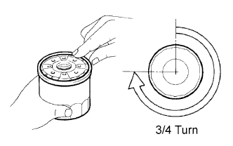
Using SST, tighten it by an additional 3/4 turn to seat the filter.
- SST
- 09228-44011
-
-
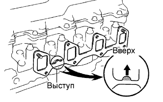
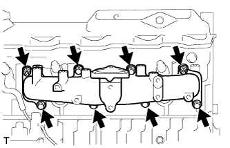
INSTALL EXHAUST MANIFOLD
-
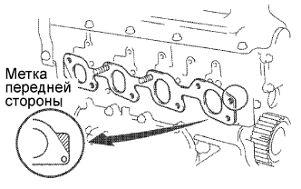
Install a new gasket to the cylinder head.
Tech Tips
Be sure to install a new gasket in the correct direction as shown in the illustration.
-
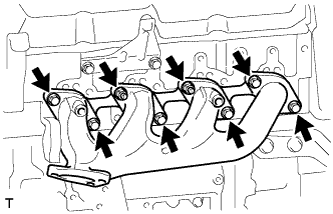
Install the exhaust manifold with the 6 bolts and 2 new nuts. Uniformly tighten the bolts and nuts in several steps.
- Torque:
- 52 N*m { 530 kgf*cm, 38 ft.*lbf }
-
-
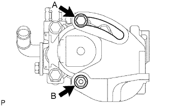
INSTALL EXHAUST MANIFOLD HEAT INSULATOR NO.1
-
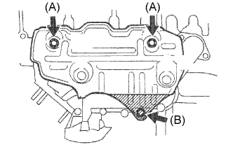
Install the heat insulator with the 3 bolts.
- Torque:
- Bolt (A)
- 18 N*m { 185 kgf*cm, 13 ft.*lbf }
- Bolt (B)
- 19 N*m { 195 kgf*cm, 14 ft.*lbf }
-
-
INSTALL OIL LEVEL GAGE GUIDE
-
Install the oil level gage guide to the cylinder head.
-
-
INSTALL OIL LEVEL GAGE SUB-ASSEMBLY
-
Install the oil level gage sub-assembly to the cylinder head.
-
-
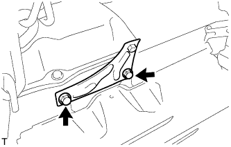
INSTALL ENGINE MOUNTING BRACKET FRONT NO.1 RH
-
Install the 6 bolts and engine mounting bracket front No.1 RH.
- Torque:
- 49 N*m { 500 kgf*cm, 36 ft.*lbf }
-
-
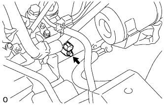
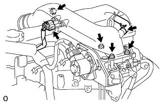
INSTALL GENERATOR W/ VACUUM PUMP ASSEMBLY
-
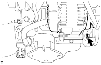
Temporarily tighten the bolt and generator w/ vacuum pump assembly.
-
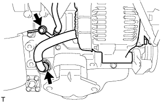
Install the clip with the hose connected.
-
Install the bolt with the hose connected.
- Torque:
- 14 N*m { 140 kgf*cm, 10 ft.*lbf }
-
-
INSTALL PUMP BRACKET
-
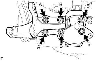
Install the 6 bolts and pump bracket.
- Torque:
- Bolt (A)
- 78 N*m { 795 kgf*cm, 58 ft.*lbf }
- Bolt (B)
- 57 N*m { 581 kgf*cm, 42 ft.*lbf }
-
-
INSTALL EXHAUST PIPE SUPPORT BRACKET NO.1
-
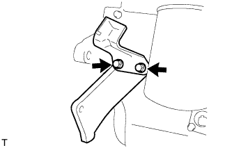
Install the 2 bolts, exhaust pipe support bracket No.1 and stiffener plate RH.
- Torque:
- 37 N*m { 377 kgf*cm, 27 ft.*lbf }
-
-
INSTALL ENGINE OIL LEVEL SENSOR
-
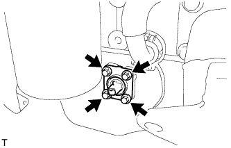
Install the 4 bolts and engine oil level sensor.
- Torque:
- 7.0 N*m { 71 kgf*cm, 62 in.*lbf }
-
-
INSTALL CYLINDER BLOCK WATER DRAIN COCK SUB-ASSEMBLY
-
Clean the threads of the water drain cock, and apply adhesive to them.
Adhesive Toyota Genuine Adhesive 1324, Three Bond 1324 or equivalent -
Install the water drain cock.
- Torque:
- 57 N*m { 581 kgf*cm, 42 ft.*lbf }
-
-
INSTALL WATER BY-PASS HOSE UNION
-
Clean the threads of the water by-pass hose union, and apply adhesive to them.
Adhesive Toyota Genuine Adhesive 1324, Three Bond 1324 or equivalent -
Install the water by-pass hose union.
- Torque:
- 39 N*m { 400 kgf*cm, 29 ft.*lbf }
-
-
INSTALL INTAKE MANIFOLD
-
Install a new gasket to the cylinder head with the protrusion facing upward.
-
Install the intake manifold with the 6 bolts and 2 nuts. Uniformly tighten the bolts and nuts in several steps.
- Torque:
- 24 N*m { 240 kgf*cm, 17 ft.*lbf }
-
-
INSTALL WATER OUTLET HOUSING
-

Install a new gasket, the water outlet and outlet hosing assembly with the 3 bolts.
- Torque:
- 19 N*m { 195 kgf*cm, 14 ft.*lbf }
-
-
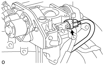
INSTALL CRANK POSITION SENSOR
-
Coat a O-ring with engine oil.
-
Install the crank position sensor with the bolt.
- Torque:
- 5.0 N*m { 51 kgf*cm, 44 in.*lbf }
-
Connect the crank position sensor connector.
-
-
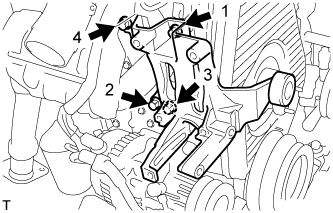
INSTALL INJECTION OR SUPPLY PUMP ASSEMBLY
-
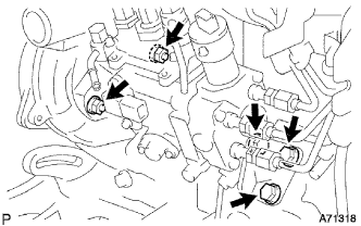
Install the injection or supply pump assembly to timing gear case, and temporarily tighten the 2 nuts.
-
Install injection pump stay No.1 to the injection or supply pump assembly rear end, and temporarily tighten the 3 bolts.
-
Rotate the pump body to make the marking of pump flange conform to the making of timing of gear case.
-
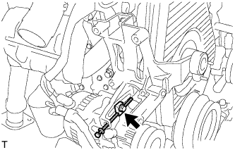
Tighten the 2 nuts to install the injection or supply pump assembly.
- Torque:
- 21 N*m { 210 kgf*cm, 15 ft.*lbf }
-
Tighten the 3 bolts to install the injection pump stay No.1.
- Torque:
- Injection pump stay No.1 x Cylinder Block
- 21 N*m { 210 kgf*cm, 15 ft.*lbf }
- Injection pump stay No.1 x Injection Pump
- 18 N*m { 185 kgf*cm, 13 ft.*lbf }
-
Connect the 3 fuel hoses.
-
Connect the engine speed sensor connector.
-
Connect the spill control valve connector.
-
Connect the correction unit connector.
-
Connect the timer control valve connector.
-
Connect the fuel temperature sensor connector.
-
Connect the engine wire clamp.
-
-
INSTALL INJECTION PUMP DRIVE PULLEY
-
Using SST, install the injection pump drive pulley with the nut.
- SST
- 09213-14010 ( 91651-60865 )
- 09330-00021
- Torque:
- 64 N*m { 650 kgf*cm, 47 ft.*lbf }
-
-
INSTALL GLOW PLUG ASSEMBLY
-
Using a 12 mm deep socket wrench, install the 4 glow plugs.
- Torque:
- 13 N*m { 130 kgf*cm, 10 ft.*lbf }
-
-
INSTALL NOZZLE HOLDER & NOZZLE SET
-
Place 4 new injection nozzle seat gaskets and 4 injection nozzle seats into the injection nozzle holes of the cylinder head.
-
Using SST, install the 4 nozzle holder and nozzle sets.
- SST
- 09268-64010 ( 09268-64020 )
- Torque:
- 64 N*m { 650 kgf*cm, 47 ft.*lbf }
-
-
INSTALL NOZZLE LEAKAGE PIPE ASSEMBLY
-
Install 4 new ring packing washers and the leakage pipe assembly with the 4 nuts.
- Torque:
- 30 N*m { 300 kgf*cm, 22 ft.*lbf }
-
Connect the fuel hose to the leakage pipe.
-
-
INSTALL GLOW PLUG NO.1 CONNECTOR
- Torque:
- 1.0 N*m { 10 kgf*cm, 9 in.*lbf }
-
INSTALL INJECTION PIPE SET
-
Connect the 2 lower clamps on the intake manifold.
-
Install the 4 injection pipes.
- Torque:
- 25 N*m { 250 kgf*cm, 18 ft.*lbf }
-
Secure the injection pipes with the 2 upper pipe clamps and 2 nuts.
- Torque:
- 5.0 N*m { 50 kgf*cm, 44 in.*lbf }
-
-
INSTALL VENTURI ASSEMBLY
-
Install a new gasket and venturi.
-
Connect the throttle control motor connector.
-
Connect the throttle open switch connector.
-
-
INSTALL INTAKE AIR CONNECTOR BRACKET
-
Install the 2 bolts and intake air connector bracket.
- Torque:
- 18 N*m { 184 kgf*cm, 13 ft.*lbf }
-
-
INSTALL INTAKE AIR CONNECTOR SUB-ASSEMBLY
-
Install a new gasket and intake air connector with the bolt and 3 nuts.
- Torque:
- bolt
- 18 N*m { 184 kgf*cm, 13 ft.*lbf }
- Nut
- 12 N*m { 122 kgf*cm, 9 ft.*lbf }
-
Connect the turbo pressure sensor connector.
-
Connect the ventilation hose.
-
-
INSTALL TIMING BELT
-
INSTALL COMPRESSOR MOUNTING BRACKET (w/ Air Conditioning)
-
Temporarily install the compressor mounting bracket with the 4 bolts.
-
Using several steps, uniformly install and tighten the 4 bolts in the sequence shown in the illustration.
- Torque:
- 85 N*m { 870 kgf*cm, 63 ft.*lbf }
-
Temporarily tighten the bolt and spacer.
-
Temporarily install the compressor mounting bracket with the 3 bolts.
-
Using several steps, uniformly install and tighten the 3 bolts in the sequence shown in the illustration.
- Torque:
- 47 N*m { 475 kgf*cm, 36 ft.*lbf }
-
-
INSTALL FAN BELT ADJUSTING BAR (w/o Air Conditioning)
-
Install the 2 bolts and fan belt adjusting bar.
- Torque:
- 45 N*m { 460 kgf*cm, 33 ft.*lbf }
-
Temporarily install the bolt.
-
-
CONNECT ENGINE MOUNTING INSULATOR FRONT
-
Connect the engine mounting insulator front with the 4 bolts.
- Torque:
- 55 N*m { 561 kgf*cm, 41 ft.*lbf }
-
-
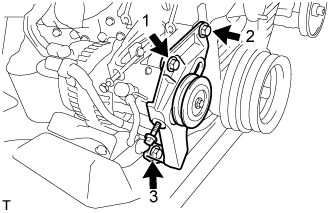
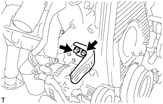
CONNECT VANE PUMP ASSEMBLY
-
Temporarily install the vane pump assembly with the 2 bolts.
-
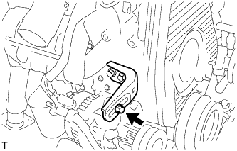
Install the pulley to the pump shaft.
-
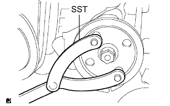
Using SST, stop the pulley rotation and torque the nut.
- SST
- 09960-10010 ( 09962-01000, 09963-01000 )
- Torque:
- 43 N*m { 440 kgf*cm, 32 ft.*lbf }
-
-
INSTALL ENGINE WIRE
-
INSTALL REAR END PLATE
-
Install the 2 bolts and rear end plate.
- Torque:
- 27 N*m { 275 kgf*cm, 19 ft.*lbf }
-
-
INSTALL FLYWHEEL SUB-ASSEMBLY
-
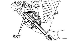
Using SST, hold the crankshaft.
- SST
- 09213-54015 ( 91651-60855 )
- 09330-00021
-
Clean the bolts and bolt holes.
-
Apply adhesive to 2 or 3 threads of the bolts.
Adhesive Toyota Genuine Adhesive 1324, Three Bond 1324 or equivalent -
Install the flywheel on the crankshaft.
-
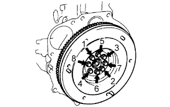
Install and uniformly tighten the 8 bolts in several steps, in the sequence shown.
- Torque:
- 123 N*m { 1,250 kgf*cm, 90 ft.*lbf }
Note
Do not start the engine within an hour after installing.
-
-
INSTALL CLUTCH DISC ASSEMBLY
-
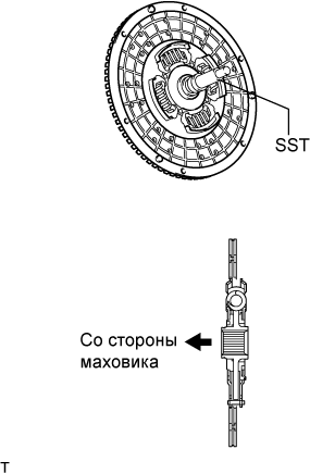
Insert SST into the clutch disc assembly, then insert them into the flywheel sub-assembly.
- SST
- 09301-00110
Note
Take care not to insert the clutch disc assembly in the wrong direction.
-
-
INSTALL CLUTCH COVER ASSEMBLY
-
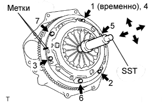
Align the matchmarks on the clutch cover assembly with the one on the flywheel sub-assembly.
-
Following the procedures shown in the illustration, tighten the 6 bolts starting from the bolt located near the knock pin on the top.
- SST
- 09301-00110
- Torque:
- 19 N*m { 195 kgf*cm, 14 ft.*lbf }
Tech Tips
-
Evenly tighten the bolts by following the order shown in the illustration.
-
Tighten the bolts after checking that the disc is in the center by lightly moving the SST up and down, left and right.
-
-
INSPECT AND ADJUST CLUTCH COVER ASSEMBLY
-
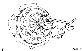
Using a dial indicator with a roller instrument, check the diaphragm spring tip alignment.
Maximum non-alignment 0.9 mm (0.035 in.) -
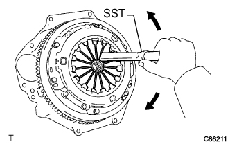
If alignment is not as specified, adjust the diaphragm spring tip alignment using SST.
- SST
- 09333-00013
-
-
INSTALL MANUAL TRANSMISSION UNIT ASSEMBLY
-
INSTALL STARTER ASSEMBLY (for 2.2 kW Type)
-
Install the starter with the 2 bolts and nut.
- Torque:
- 69 N*m { 700 kgf*cm, 51 ft.*lbf }
-
Install the stay with the 2 bolts and nut.
- Torque:
- 69 N*m { 104 kgf*cm, 51 ft.*lbf }
-
Connect the 30 terminal with the nut.
- Torque:
- 9.8 N*m { 100 kgf*cm, 7 ft.*lbf }
-
Install the terminal cap.
-
Connect the starter connector.
-
-
INSTALL STARTER ASSEMBLY (for 2.7 kW Type)
-
Install the starter with the 2 bolts, nut and stay.
- Torque:
- 69 N*m { 700 kgf*cm, 51 ft.*lbf }
-
Install the starter stay with the 2 bolts and nut.
- Torque:
- Bolt
- 37 N*m { 380 kgf*cm, 27 ft.*lbf }
- Nut
- 12.5 N*m { 130 kgf*cm, 9 ft.*lbf }
-
Connect the 30 terminal with the nut.
- Torque:
- 21 N*m { 215 kgf*cm, 16 ft.*lbf }
-
Install the terminal cap.
-
Connect the starter connector.
-
-
INSTALL ENGINE W/ TRANSMISSION ASSEMBLY
-
Using the engine lifter, install the engine w/ transmission assembly to the vehicle.
-
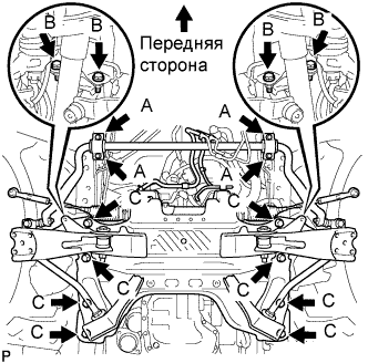
Install the 4 bolts and stabilizer bracket.
- Torque:
- Bolt (A)
- 36 N*m { 367 kgf*cm, 27 ft.*lbf }
-
Install the 16 bolts and front suspension cross member.
- Torque:
- Bolt (B)
- 39 N*m { 398 kgf*cm, 29 ft.*lbf }
- Bolt (C)
- 150 N*m { 1,530 kgf*cm, 111 ft.*lbf }
-
Connect the rear engine mounting.
- Torque:
- 98 N*m { 1,000 kgf*cm, 72 ft.*lbf }
Note
Tighten the nuts when install the engine mounting.
-
Remove the engine lifter.
-
-
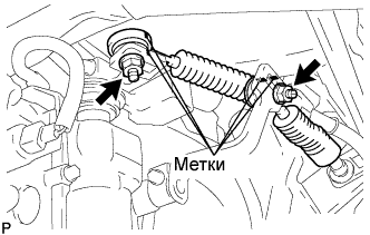
CONNECT STEERING TORQUE SHAFT ASSEMBLY
-
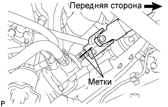
Совместите метки на крутящем валу рулевого управления в сборе и тяге рулевого управления с усилителем в сборе.
-
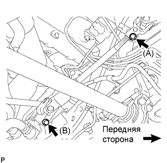
Вверните болт (B) и затяните 2 болта.
- Torque:
- 35 Н*м { 360 кгс*см, 26 фунт-сила-футов }
-
-
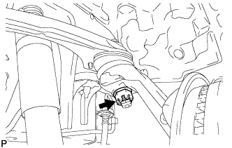
CONNECT CLUTCH RELEASE CYLINDER ASSEMBLY
-
Install the clutch release cylinder with the 2 bolts.
- Torque:
- 12 N*m { 120 kgf*cm, 9 ft.*lbf }
-
-
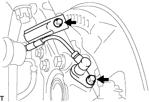
CONNECT WIRE HARNESS
-
Connect the 2 connectors and clamp.
-
-
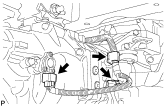
CONNECT TRANSMISSION CONTROL CABLE ASSEMBLY
-
Install 2 new clips to the transmission control cable bracket No.1.
-
Install the transmission control cable assembly to the transmission control cable bracket No.1.
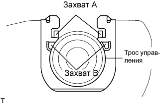
Note
-
Be sure that A claws of the clips are firmly engaged into the bracket grooves.
-
Be sure the cable is set in the clip with both B claws erected to prevent slippage of the cable in the opposite direction.
-
-
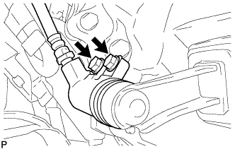
Align the matchmarks on the control cable assembly and the outer lever.
-
Install the transmission control cable assembly to the outer levers with the 2 nuts.
- Torque:
- 37 N*m { 377 kgf*cm, 27 ft.*lbf }
-
-
CONNECT SHOCK ABSORBER ASSEMBLY FRONT LH
-
CONNECT SHOCK ABSORBER ASSEMBLY FRONT RH
Tech Tips
Use the same procedures described for the LH side.
-
CONNECT FRONT SUSPENSION ARM SUB-ASSEMBLY UPPER LH
-
Подсоедините верхний рычаг передней подвески к поворотному кулаку и закрепите гайкой.
- Torque:
- 113 Н*м { 1150 кгс*см, 83 фунт-сила-фута }
-
Установите новый шплинт.
Note
-
Если отверстия под шплинт не совпадают, затяните гайку на угол до 60°.
-
Старайтесь не повредить защитный кожух шарового шарнира.
-
-
-
CONNECT FRONT SUSPENSION ARM SUB-ASSEMBLY UPPER RH
Tech Tips
Use the same procedures described for the LH side.
-
INSTALL FRONT DISC BRAKE CALIPER ASSEMBLY LH
-
Установите суппорт тормоза в сборе на поворотный кулак и закрепите 2 болтами.
- Torque:
- 123 Н*м { 1250 кгс*см, 91 фунт-сила-фут }
-
-
INSTALL FRONT DISC BRAKE CALIPER ASSEMBLY RH
Tech Tips
Use the same procedures described for the LH side.
-
INSTALL SPEED SENSOR FRONT LH (w/ ABS)
-
Установите датчик частоты вращения на поворотный кулак и закрепите его 2 болтами.
- Torque:
- 8,5 Н*м { 87 кгс*см, 75 фунт-сила-дюймов }
Note
-
Не допускайте налипания на датчик частоты вращения посторонних частиц.
-
Будьте осторожны, чтобы не повредить датчик частоты вращения.
-
Не допускайте перекручивания провода датчика частоты вращения при установке.
-
-
INSTALL SPEED SENSOR FRONT RH (w/ ABS)
Tech Tips
Use the same procedures described for the LH side.
-
INSTALL PROPELLER SHAFT ASSEMBLY (for Long Wheelbase)
-
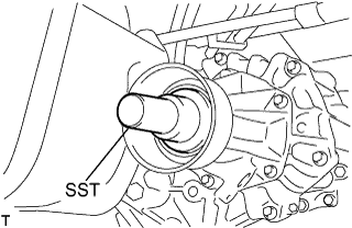
Снимите SST с удлинителя картера трансмиссии.
-
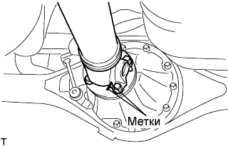
Установите карданный вал в сборе в удлинитель картера трансмиссии.
-
Совместите метки на фланце карданного вала и фланце дифференциала.
-
Закрепите карданный вал в сборе с помощью 4 гаек, 4 болтов и 4 шайб.
- Torque:
- 74 Н*м { 755 кгс*см, 54 фунт-сила-фута }
-
-
INSTALL PROPELLER SHAFT ASSEMBLY (for Super Long Wheelbase)
-
Снимите SST с удлинителя картера трансмиссии.
-
Установите карданный вал с центральным подшипником в сборе в удлинитель картера трансмиссии.
-
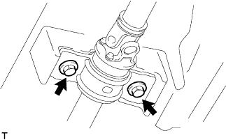
Установите центральный опорный подшипник № 1 в сборе и временно затяните 2 болта.
-
Совместите метки на фланце карданного вала и фланце дифференциала.
-
Закрепите карданный вал в сборе с помощью 4 гаек, 4 болтов и 4 шайб.
- Torque:
- 74 Н*м { 755 кгс*см, 54 фунт-сила-фута }
-
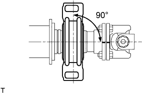
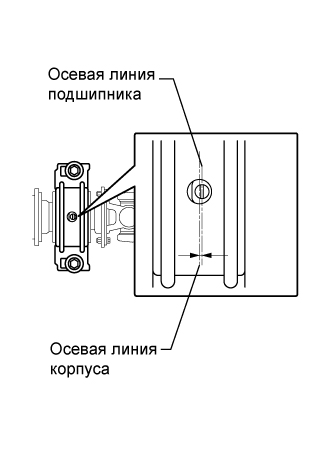
Осевая линия кронштейна должна проходить под прямым углом к осевому направлению вала.
-
Отрегулируйте центральный опорный подшипник № 1 в сборе.
Tech Tips
-
Отрегулируйте центральный опорный подшипник № 1 для установки углов на порожнем автомобиле, как показано на рисунке.
-
В таких же условиях проверьте осевую линию в осевом направлении. При необходимости отрегулируйте положение подшипника.
-
Осевая линия центрального подшипника и осевая линия корпуса центрального подшипника должны быть отрегулированы таким образом, чтобы расстояние между ними попадало в диапазон -1,0-1,0 мм (-0,0394-0,0394 дюйма) в продольном направлении (вдоль автомобиля) в разгруженном состоянии автомобиля.
-
-
Затяните 2 болта.
- Torque:
- 36 Н*м { 369 кгс*см, 27 фунт-сила-футов }
-
-
INSTALL EXHAUST PIPE SUB-ASSEMBLY FRONT NO.1 (for Long Wheelbase)
-
Install a new gasket and exhaust pipe sub-assembly front No.1 with the 3 bolts.
- Torque:
- 62 N*m { 632 kgf*cm, 46 ft.*lbf }
-
Tighten the clamp bolt, and install the exhaust pipe support bracket No.1 to the exhaust pipe sub-assembly front No.1.
-
-
INSTALL EXHAUST PIPE SUB-ASSEMBLY FRONT NO.1 (for Super Long Wheelbase)
-
Install a new gasket and exhaust pipe sub-assembly front No.1 with the 3 bolts.
- Torque:
- 62 N*m { 632 kgf*cm, 46 ft.*lbf }
-
Tighten the clamp bolt, install the exhaust pipe support bracket No.1 to the exhaust pipe sub-assembly front No.1.
-
-
INSTALL EXHAUST PIPE SUB-ASSEMBLY FRONT NO.2 (for Long Wheelbase)
-
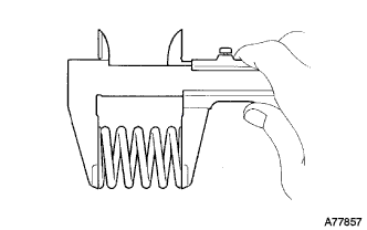
Inspect the compression spring.
-
Using vernier calipers, measure the free length of the compression springs.
Minimum length 40.5 mm (1.594 in.) Tech Tips
If the free length is less than the minimum, replace the compression spring.
-
-
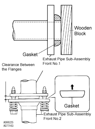
Install the gasket.
-
Fully insert a new gasket to the exhaust pipe sub-assembly front No.1 by hand.
-
Using a wooden block, uniformly strike the gasket so that the gasket and exhaust pipe sub-assembly front No.1 are properly fit.
Note
-
Be careful with the installation direction of the gasket.
-
Do not damage the outer face.
-
Do not reuse the gasket.
-
To ensure a proper seal, do not use the exhaust pipe sub-assembly front No.2 to force the gasket onto the exhaust pipe sub-assembly front No.1.
-
-
-
Connect the exhaust pipe support, and install a new gasket and the exhaust pipe sub-assembly front No.2 with the 4 bolts, 2 nuts, and 2 compression springs.
- Torque:
- Exhaust pipe sub-assembly front No.1 side
- 43 N*m { 438 kgf*cm, 32 ft.*lbf }
- Exhaust pipe assembly tail side
- 48 N*m { 489 kgf*cm, 35 ft.*lbf }
Note
After installation, check that the clearance is almost same at any point between the flanges of the exhaust pipe sub-assembly front No.2 and exhaust pipe sub-assembly front No.1.
-
-
INSTALL EXHAUST PIPE SUB-ASSEMBLY FRONT NO.2 (for Super Long Wheelbase)
-
Inspect the compression spring.
-
Using vernier calipers, measure the free length of the compression springs.
Minimum length 40.5 mm (1.594 in.) Tech Tips
If the free length is less than the minimum, replace the compression spring.
-
-
Install the gasket.
-
Fully insert a new gasket to the exhaust pipe sub-assembly front No.1 by hand.
-
Using a wooden block, uniformly strike the gasket so that the gasket and exhaust pipe sub-assembly front No.1 are properly fit.
Note
-
Be careful with the installation direction of the gasket.
-
Do not damage the gasket.
-
Do not reuse the gasket.
-
To ensure a proper seal, do not use the exhaust pipe sub-assembly front No.2 to force the gasket onto the exhaust pipe sub-assembly front No.1.
-
-
-
Connect the exhaust pipe support, and install a new gasket and the exhaust pipe sub-assembly front No.2 with the 4 bolts, 2 nuts, and 2 compression springs.
- Torque:
- Exhaust pipe sub-assembly front No.1 side
- 43 N*m { 438 kgf*cm, 32 ft.*lbf }
- Exhaust pipe assembly center side
- 48 N*m { 489 kgf*cm, 35 ft.*lbf }
Note
After installation, check that the clearance is almost same at any point between the flanges of the exhaust pipe sub-assembly front No.2 and exhaust pipe sub-assembly front No.1 .
-
-
CONNECT ENGINE WIRE
-
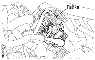
Install the connector and nut, as shown the illustration.
-
Install the nut then remove the starter wire harness.
- Torque:
- 9.8 N*m { 100 kgf*cm, 87 in.*lbf }
-
Connect the clamp and ground cable of the engine wire.
-
Connect the ECM connector Click here.
-
-
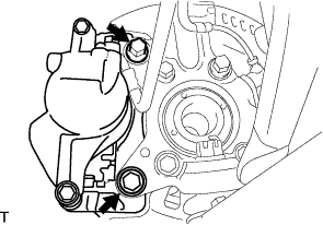
CONNECT VANE PUMP OIL RESERVOIR ASSEMBLY
-
Установите масляный бачок лопастного насоса в сборе и закрепите 2 болтами.
- Torque:
- 8,0 Н*м { 82 кгс*см, 71 фунт-сила-дюйм }
-
-
INSTALL COMPRESSOR AND MAGNETIC CLUTCH
-
CONNECT AIR CLEANER HOSE NO.2
-
Install the air cleaner hose No.2 with the clamp.
-
-
CONNECT INJECTION PUMP TO FUEL FILTER FUEL HOSE OR PIPE
-
CONNECT RADIATOR HOSE NO.4
-
CONNECT RADIATOR HOSE INLET
-
INSTALL FAN & GENERATOR V BELT (w/o Air Conditioning)
-
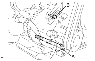
Установите поликлиновой ремень.
-
Отрегулируйте натяжение поликлинового ремня с помощью стержня.
-
Затяните болты А и В.
- Torque:
- Болт A
- 75 Н*м { 765 кгс*см, 55 фунт-сила-фута }
- Болт B
- 18 Н*м { 185 кгс*см, 13 фунт-сила-футов }
-
Проверьте натяжение поликлинового ремня. (см. стр. Click here)
-
-
INSTALL FAN & GENERATOR V BELT (w/ Air Conditioning)
-
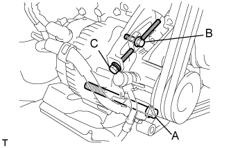
Установите поликлиновой ремень.
-
Отрегулируйте натяжение поликлинового ремня с помощью болта C.
-
Затяните болты А и В.
- Torque:
- Болт A
- 75 Н*м { 765 кгс*см, 55 фунт-сила-футов }
- Болт B
- 18 Н*м { 185 кгс*см, 13 фунт-сила-футов }
-
Проверьте натяжение поликлинового ремня. (см. стр. Click here)
-
-
INSTALL V (COOLER COMPRESSOR TO CRANKSHAFT PULLEY) BELT NO.1
-
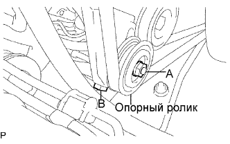
Установите поликлиновой ремень.
-
Затягивая болт В, отрегулируйте натяжение поликлинового ремня.
-
Затяните гайку А.
- Torque:
- 39 Н*м { 400 кгс*см, 29 фунт-сила-футов }
-
Проверьте натяжение поликлинового ремня. (см. стр. Click here)
-
-
INSTALL VANE PUMP V BELT
-
Установите поликлиновой ремень.
-
Отрегулируйте натяжение поликлинового ремня с помощью стержня.
-
Затяните болт А и гайку В.
- Torque:
- Болт (A)
- 48 Н*м { 489 кгс*см, 35 фунт-сила-футов }
- Гайка (B)
- 64 Н*м { 635 кгс*см, 47 фунт-сила-дюймов }
-
Проверьте натяжение поликлинового ремня. (см. стр. Click here)
-
-
INSTALL ENGINE SERVICE HOLE SUB COVER SUB-ASSEMBLY
-
Install the 5 bolts and engine service hole cover.
- Torque:
- 13 N*m { 133 kgf*cm, 10 ft.*lbf }
-
-
INSTALL FRONT DOOR SCUFF PLATE RH
-
INSTALL FRONT SEAT ASSEMBLY RH (for Hi-back Seat Type)
Use the same procedures described for the LH side. Click here
-
INSTALL FRONT SEAT ASSEMBLY RH (for Low-back Seat Type)
Use the same procedures described for the LH side. Click here
-
CONNECT CABLE TO NEGATIVE BATTERY TERMINAL
-
INSTALL FRONT WHEEL
-
PLACE FRONT WHEELS FACING STRAIGHT AHEAD
-
ADD ENGINE OIL
-
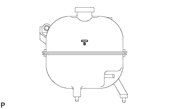
ADD ENGINE COOLANT
-
Залейте охлаждающую жидкость в расширительный бачок радиатора до верха горловины.
Номинальный объем Параметр / Устройство Заданные условия Для моделей без подогревателя 12,3 литра (13,0 кварты США, 10,8 английской кварты) Для моделей с передним подогревателем 13,3 литра (14,1 кварты США, 11,7 английской кварты) Для моделей с передним и задним подогревателями 15,3 литра (16,2 кварты США, 13,5 английской кварты) Note
Не доливайте простую воду вместо охлаждающей жидкости двигателя.
Tech Tips
-
Использование неподходящей охлаждающей жидкости может привести к повреждению системы охлаждения двигателя.
-
Разрешается использовать только охлаждающую жидкость "TOYOTA Super Long Life Coolant" или аналогичную высококачественную охлаждающую жидкость на основе этиленгликоля (а не на силикатной, аминовой, нитритной или борнокислой основе), изготовленную по гибридной технологии органических кислот с длительным сроком годности (охлаждающая жидкость, изготовленная по гибридной технологии органических кислот, состоит из низкофосфатных соединений и органических кислот).
-
-
Долейте охлаждающую жидкость в расширительный бачок радиатора до отметки B и установите пробку расширительного бачка радиатора.
-
Прогревайте двигатель, пока не откроется термостат.
-
Когда термостат откроется, несколько минут прокачивайте охлаждающую жидкость.
Tech Tips
Время открывания термостата можно проверить, сжав входной патрубок радиатора рукой и убедившись, что охлаждающая жидкость поступает в шланг.
-
-
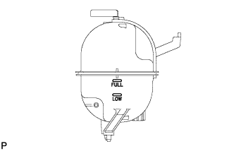
После охлаждения двигателя убедитесь, что уровень охлаждающей жидкости находится между отметками "LOW" и "FULL".
-
-
BLEED AIR FROM FUEL SYSTEM
-
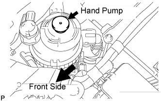
Using the hand pump, bleed air from the fuel system until pumping becomes difficult.
-
-
CHECK FUEL LEAK
-
Check that there are no fuel leaks anywhere on the fuel system after doing maintenance.
Tech Tips
When checking for fuel leaks, make sure that there is pressure in the fuel line.
-
-
CHECK FOR ENGINE OIL LEAKS
-
CHECK FOR ENGINE COOLANT LEAKS
CAUTION:
Не снимайте пробку радиатора, пока двигатель и радиатор не остынут. Выброс горячей охлаждающей жидкости и пара под давлением может стать причиной серьезных ожогов.
-
Заполните радиатор охлаждающей жидкостью и подсоедините к радиатору приспособление для опрессовки системы охлаждения и проверки пробки радиатора.
-
Прогрейте двигатель.
-
С помощью приспособления для опрессовки системы охлаждения и проверки пробки радиатора увеличьте давление в радиаторе до 118 кПа (1,2 кгс/см2, 17,1 фунтов на кв. дюйм) и убедитесь, что давление не падает.
Tech Tips
Если давление снижается, проверьте на наличие утечек шланги, радиатор и насос системы охлаждения. При отсутствии внешних утечек проверьте сердцевину отопителя, блок цилиндров и головку блока цилиндров.
-
-
CHECK TRANSMISSION OIL
-
Установить автомобиль на ровной горизонтальной площадке.
-
Снимите пробку наливной горловины трансмиссии и прокладку.
-
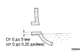
Убедитесь в том, что поверхность масла попадает в зону 5 мм (0,20 дюйма) у нижнего края наливного отверстия трансмиссии.
Класс масла по степени вязкости GL-4 Вязкость SAE 75W-90 Объем 2,2 л (2,3 кварты США, 1,9 английской кварты) Note
-
Если уровень масла слишком низкий или чрезмерно высокий, работа системы может быть нарушена.
-
После замены масла совершите пробную поездку на автомобиле, а затем снова проверьте уровень масла.
-
-
Если уровень масла низкий, проверьте, нет ли утечек.
-
Установите на место пробку наливной горловины трансмиссии и новую прокладку.
- Torque:
- 37 Н*м { 377 кгс*см, 27 фунт-сила-футов }
-
-
CHECK FOR EXHAUST GAS LEAKS
-
ADJUST FRONT WHEEL ALIGNMENT
-
CHECK IDLE SPEED
-
Warm up the engine.
-
When using an intelligent tester:
-
Connect the intelligent tester to the DLC3.
Idle speed 720 to 820 rpm (A/C OFF) 750 to 850 rpm (A/C ON) Tech Tips
Refer to the intelligent tester operator's manual for further details.
-
-
When not using an intelligent tester:
-
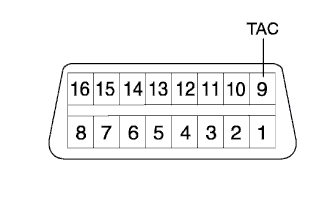
Using SST, connect the tachometer test probe to terminal 9 (TAC) of the DLC3.
- SST
- 09843-18040
-
Check the idle speed.
Idle speed 720 to 820 rpm (A/C OFF) 750 to 850 rpm (A/C ON) Note
Switch off all accessories.
-
-
-
INSPECT MAXIMUM ENGINE SPEED
-
Start the engine.
-
Depress the accelerator pedal all the way.
-
Check the maximum speed.
Maximum speed 4,850 to 4,950 rpm
-
-
CHECK ABS SENSOR SIGNAL
-
PERFORM INITIALIZATION