СИСТЕМА ECD Цепь контрольной лампы неисправности MIL
DESCRIPTION
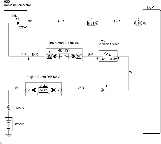
The Malfunction Indicator Lamp (MIL) is used to indicate the ECM's detection of a vehicle malfunction. The instrument panel J/B MET IGN fuse provides circuit power and the ECM provides the circuit ground that illuminates the MIL.
MIL operations should be checked visually:
The MIL should be illuminated when the ignition switch is first turned ON. If the MIL is always on or off, use the intelligent tester and follow the procedures below to determine the cause of the problem.
WIRING DIAGRAM
INSPECTION PROCEDURE
PROCEDURE
-
CHECK MIL
-
Turn the ignition switch ON.
Result MIL Condition Proceed MIL is illuminated A MIL is not illuminated B
B : 
INSPECT ECM (CHECK VOLTAGE) Click here
A : 
-
-
CLEAR DTC
-
Connect the intelligent tester to the DLC3.
-
Turn the ignition switch ON and push the intelligent tester main switch on.
-
Read the DTC Click here.
-
Clear the DTC Click here.
-
Check that MIL is not illuminated.
OK MIL is not illuminated.
NG :
CHECK WIRE HARNESS (FOR SHORT IN WIRE CIRCUIT) Click here
OK :REPAIR CIRCUIT INDICATED BY OUTPUT DTC 
REPAIR CIRCUIT INDICATED BY OUTPUT DTC
-
-
CHECK WIRE HARNESS (FOR SHORT IN WIRE CIRCUIT)
-
Disconnect the B10 ECM connector.
-
Turn the ignition switch ON.
-
Check that MIL is not illuminated.
OK MIL is not illuminated.
NG :
CHECK HARNESS AND CONNECTOR (ECM - COMBINATION METER) Click here
OK :REPLACE ECM
REPLACE ECM
-
-
CHECK HARNESS AND CONNECTOR (ECM - COMBINATION METER)
-
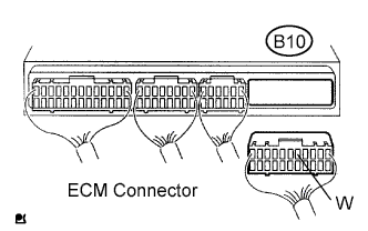
Disconnect the ECM B10 connector.
-
Measure the resistance according to the value(s) in the table below.
Standard resistance (Check for short) Tester Connection Specified condition W (B10-5) - Body ground 10 kΩ or higher
NG :REPAIR OR REPLACE HARNESS OR CONNECTOR 
REPAIR OR REPLACE HARNESS OR CONNECTOR
OK :ПРОВЕРЬТЕ, НЕТ ЛИ ЭПИЗОДИЧЕСКИХ НЕИСПРАВНОСТЕЙ
ПРОВЕРЬТЕ, НЕТ ЛИ ЭПИЗОДИЧЕСКИХ НЕИСПРАВНОСТЕЙ
-
-
INSPECT ECM (CHECK VOLTAGE)
-
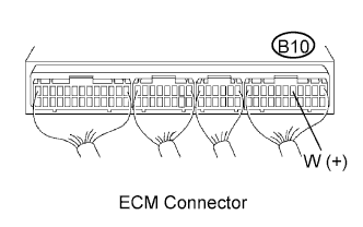
Turn the ignition switch ON.
-
Measure the voltage according to the value(s) in the table below.
Standard voltage Tester Connection Specified condition W (B10-5) - Body ground 9 to 14 V
NG :
INSPECT COMBINATION METER (CHECK VOLTAGE) Click here
OK :REPLACE ECM
REPLACE ECM
-
-
INSPECT COMBINATION METER (CHECK VOLTAGE)
-
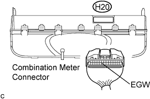
Disconnect the combination meter connector.
-
Turn the ignition switch ON.
-
Measure the voltage according to the value(s) in the table below.
Standard voltage Tester Connection Specified condition EGW (H20-32) - Body ground 9 to 14 V
NG :
INSPECT COMBINATION METER (CHECK VOLTAGE) Click here
OK :
-
-
CHECK HARNESS AND CONNECTOR (ECM - COMBINATION METER)
-
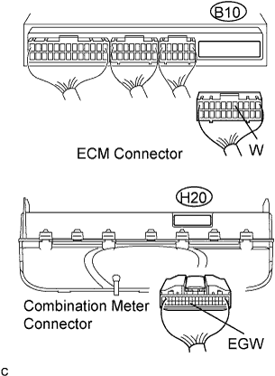
Disconnect the combination meter connector.
-
Disconnect the ECM B10 connector.
-
Measure the resistance according to the value(s) in the table below.
Standard resistance (Check for open) Tester Connection Specified condition EGW (H20-32) - W (B10-5) Below 1 Ω
NG :REPAIR OR REPLACE HARNESS OR CONNECTOR
REPAIR OR REPLACE HARNESS OR CONNECTOR
OK :ПРОВЕРЬТЕ, НЕТ ЛИ ЭПИЗОДИЧЕСКИХ НЕИСПРАВНОСТЕЙ
ПРОВЕРЬТЕ, НЕТ ЛИ ЭПИЗОДИЧЕСКИХ НЕИСПРАВНОСТЕЙ
-
-
INSPECT COMBINATION METER (CHECK VOLTAGE)
-
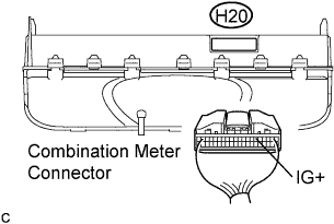
Disconnect the combination meter connector.
-
Turn the ignition switch ON.
-
Measure the voltage according to the value(s) in the table below.
Standard voltage Tester Connection Specified condition IG+ (H20-6) - Body ground 9 to 14 V
NG :
CHECK FUSE (MET IGN FUSE) Click here
OK :REPLACE COMBINATION METER
REPLACE COMBINATION METER
-
-
CHECK FUSE (MET IGN FUSE)
-
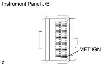
Remove the MET IGN fuse from the instrument panel J/B.
-
Measure the resistance according to the value(s) in the table below.
Standard resistance Tester Connection Specified Condition MET IGN fuse Below 1 Ω (Continuity)
NG :REPLACE FUSE (MET IGN FUSE)
REPLACE FUSE (MET IGN FUSE)
OK :
-
-
CHECK HARNESS AND CONNECTOR (COMBINATION METER - MET IGN FUSE)
-
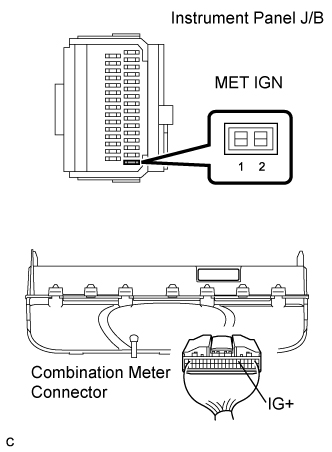
Disconnect the combination meter connectors.
-
Remove the MET IGN fuse from the instrument panel J/B.
-
Measure the resistance according to the value(s) in the table below.
Standard resistance (Check for open) Tester Connection Specified condition (MET IGN fuse terminal 1 of J/B) - IG+ (H20-6) Below 1 Ω
NG :REPAIR OR REPLACE HARNESS OR CONNECTOR
REPAIR OR REPLACE HARNESS OR CONNECTOR
OK :CHECK AND REPLACE HARNESS AND CONNECTOR (MET IGN FUSE - BATTERY)
CHECK AND REPLACE HARNESS AND CONNECTOR (MET IGN FUSE - BATTERY)
-