СИСТЕМА ECD Цепь сигнала системы кондиционирования
DESCRIPTION
When the A/C compressor is on, the A/C amplifier sends the A/C signal to the ECM, then ECM increases the fuel injection volume to improve driveability during engine idling.
WIRING DIAGRAM
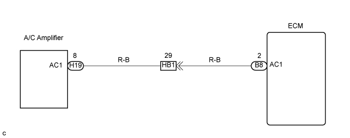
INSPECTION PROCEDURE
When using intelligent tester:
PROCEDURE
-
READ VALUE USING INTELLIGENT TESTER (AIR CONDITIONER SIGNAL)
-
Connect the intelligent tester to the DLC3.
-
Start the engine.
-
Air conditioning switch on.
-
Select the item "Powertrain/Engine and ECT/Data List/A/C Signal" and read its value displayed on the intelligent tester.
Result A/C Compressor Display OFF A/C Signal OFF ON A/C Signal ON
NG : 
INSPECT ECM (CHECK VOLTAGE) Click here
OK :PROCEED TO NEXT CIRCUIT INSPECTION SHOWN IN PROBLEM SYMPTOMS TABLE 
PROCEED TO NEXT CIRCUIT INSPECTION SHOWN IN PROBLEM SYMPTOMS TABLE
-
-
INSPECT ECM (CHECK VOLTAGE)
-
Start the engine.
-
Measure the voltage according to the value(s) in the table below.
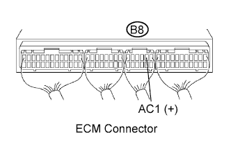
Standard voltage Tester Connection Connection Specified Condition AC1 (B8-2) - Body ground A/C compressor ON Below 1.5 V AC1 (B8-2) - Body ground A/C compressor OFF 7.5 to 14 V
NG :
CHECK HARNESS AND CONNECTOR (ECM - AIR CONDITIONER AMPLIFIER) Click here
OK :REPLACE ECM
REPLACE ECM
-
-
CHECK HARNESS AND CONNECTOR (ECM - AIR CONDITIONER AMPLIFIER)
-
Disconnect the A/C amplifier H19 connector.
-
Disconnect the ECM B8 connector.
-
Measure the resistance according to the value(s) in the table below.
Standard resistance (Check for open) Tester Connection Specified Condition AC1 (H19-8) (*1) - AC1 (B8-2)
Below 1 Ω Standard resistance (Check for short) Tester Connection Specified Condition AC1 (B8-2) - Body ground 10 kΩ or higher Tech Tips
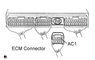
*1: Terminal arrangement Click here.
NG :REPAIR OR REPLACE HARNESS OR CONNECTOR 
REPAIR OR REPLACE HARNESS OR CONNECTOR
OK :REPLACE AIR CONDITIONER AMPLIFIER
REPLACE AIR CONDITIONER AMPLIFIER
-
When not using intelligent tester:
PROCEDURE
-
INSPECT ECM (CHECK VOLTAGE)
-
Start the engine.
-
Measure the voltage according to the value(s) in the table below.
Standard voltage Tester Connection Connection Specified Condition AC1 (B8-2) - Body ground A/C compressor ON Below 1.5 V AC1 (B8-2) - Body ground A/C compressor OFF 7.5 to 14 V
NG :
CHECK HARNESS AND CONNECTOR (ECM - AIR CONDITIONER AMPLIFIER) Click here
OK :PROCEED TO NEXT CIRCUIT INSPECTION SHOWN IN PROBLEM SYMPTOMS TABLE
PROCEED TO NEXT CIRCUIT INSPECTION SHOWN IN PROBLEM SYMPTOMS TABLE
-
-
CHECK HARNESS AND CONNECTOR (ECM - AIR CONDITIONER AMPLIFIER)
-
Disconnect the A/C amplifier H19 connector.
-
Disconnect the ECM B8 connector.
-
Measure the resistance according to the value(s) in the table below.
Standard resistance (Check for open) Tester Connection Specified Condition AC1 (H19-8) (*1) - AC1 (B8-2)
Below 1 Ω Standard resistance (Check for short) Tester Connection Specified Condition AC1 (B8-2) - Body ground 10 kΩ or higher Tech Tips
*1: Terminal arrangement Click here.
NG :REPAIR OR REPLACE HARNESS OR CONNECTOR
REPAIR OR REPLACE HARNESS OR CONNECTOR
OK :REPLACE AIR CONDITIONER AMPLIFIER
REPLACE AIR CONDITIONER AMPLIFIER
-