СИСТЕМА ECD ECM Power Source Circuit
DESCRIPTION
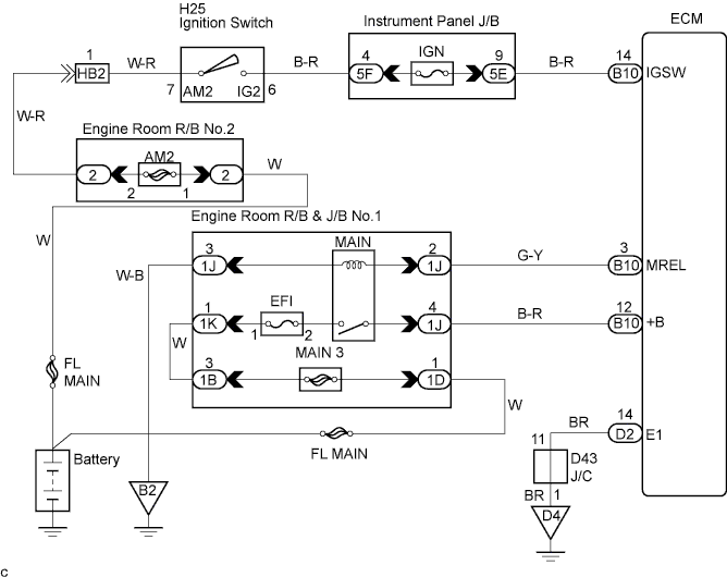
When the ignition switch is turned ON, battery positive voltage is applied to the coil, closing the contacts of the MAIN relay (Marking: MAIN) and supplying power to the terminal +B of the ECM.
WIRING DIAGRAM
INSPECTION PROCEDURE
PROCEDURE
-
INSPECT ECM (CHECK VOLTAGE)
-

Turn the ignition switch ON.
-
Measure the voltage according to the value(s) in the table below.
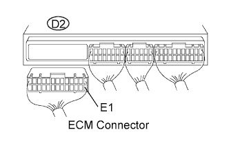
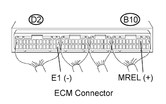
Standard voltage Tester Connection Specified Condition +B (B10-12) - E1 (D2-14) 9 to 14 V
NG 
CHECK HARNESS AND CONNECTOR (ECM - BODY GROUND) Click here
OK 
PROCEED TO NEXT CIRCUIT INSPECTION SHOWN IN PROBLEM SYMPTOMS TABLE
-
-
CHECK HARNESS AND CONNECTOR (ECM - BODY GROUND)
-
Disconnect the ECM D2 connector.
-
Measure the resistance according to the value(s) in the table below.
Standard resistance (Check for open) Tester Connection Specified Condition E1 (D2-14) - Body ground Below 1 Ω
NG 
REPAIR OR REPLACE HARNESS OR CONNECTOR
OK 
-
-
INSPECT INTEGRATION NO.1 RELAY (MAIN RELAY)
-
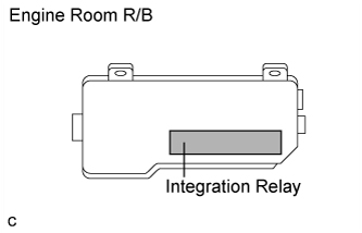
Check that operation sound is heard from the integration relay (MAIN relay) in connection with the operation (on/off) of the ignition switch.
OK Operation sound can be heard.
NG
INSPECT ECM (CHECK VOLTAGE) Click here
OK
-
-
CHECK HARNESS AND CONNECTOR (ECM - BATTERY)
-
Disconnect the battery negative cable.
-
Disconnect the battery positive cable.
-
Disconnect the engine room R/B & J/B No.1 1B, 1J and 1K connectors.
-
Disconnect the engine room R/B & J/B No.1 1D connector.
-
Disconnect the ECM B10 connector.
-
Measure the resistance according to the value(s) in the table below.
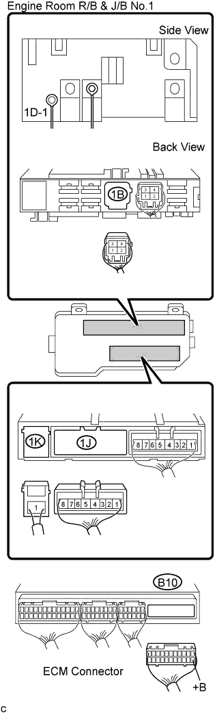
Standard resistance Tester Connection Specified Condition +B (B10-12) - (1J-4) Below 1 Ω (1K-1) - (1B-3) Below 1 Ω (1D-1) - Positive terminal of the battery Below 1 Ω Note
After reconnecting the battery cable, the radio and clock should be adjusted as they were previously.
NG
REPAIR OR REPLACE HARNESS OR CONNECTOR
OK
REPLACE INTEGRATION NO.1 RELAY
-
-
INSPECT ECM (CHECK VOLTAGE)
-
Turn the ignition switch ON.
-
Measure the voltage according to the value(s) in the table below.
Standard voltage Tester Connection Specified Condition MREL (B10-3) - E1 (D2-14) 9 to 14 V
NG
INSPECT ECM (CHECK VOLTAGE) Click here
OK
-
-
CHECK HARNESS AND CONNECTOR (ECM - BODY GROUND)
-
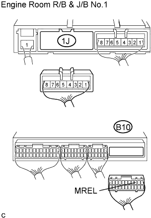
Disconnect the ECM B10 connector.
-
Disconnect the engine room R/B & J/B No.1 1J connector.
-
Measure the resistance according to the value(s) in the table below.
Standard resistance (Check for open) Tester Connection Specified Condition MREL (B10-3) - (1J-2) Below 1 Ω (1J-3) - Body ground Below 1 Ω
NG
REPAIR OR REPLACE HARNESS OR CONNECTOR
OK
REPLACE INTEGRATION NO.1 RELAY
-
-
INSPECT ECM (CHECK VOLTAGE)
-
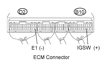
Turn the ignition switch ON.
-
Measure the voltage according to the value (s) in the table below.
Standard voltage Tester Connection Specified Condition IGSW (B10-14) - E1 (D2-14) 9 to 14 V
NG
CHECK FUSE (IGN FUSE) Click here
OK
REPLACE ECM
-
-
CHECK FUSE (IGN FUSE)
-
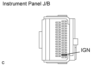
Remove the IGN fuse from the instrument panel J/B.
-
Measure the resistance according to the value(s) in the table below.
Standard resistance Tester Connection Specified Condition IGN fuse Below 1 Ω (Continuity)
NG
REPLACE FUSE (IGN FUSE)
OK
-
-
INSPECT IGNITION SWITCH
-
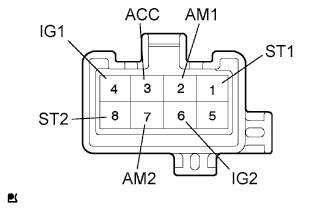
Disconnect the ignition switch connector.
-
Measure the resistance according to the value(s) in the table below.
Standard resistance (Ignition switch position is LOCK) Tester Connection Specified Condition All terminals 10 kΩ or higher Standard resistance (Ignition switch position is ACC) Tester Connection Specified Condition 2 - 3 Below 1 Ω Standard resistance (Ignition switch position is ON) Tester Connection Specified Condition 2 - 3 - 4 Below 1 Ω 6 - 7 Below 1 Ω Standard resistance (Ignition switch position is START) Tester Connection Specified Condition 1 - 2 - 4 Below 1 Ω 7 - 8 Below 1 Ω
NG
REPLACE IGNITION SWITCH
OK
CHECK AND REPLACE HARNESS AND CONNECTOR (ECM - BATTERY)
-