СИСТЕМА ECD, Diagnostic DTC:42
| DTC Code | DTC Name |
|---|---|
| 42 | Vehicle Speed Sensor Signal Circuit Malfunction |
DESCRIPTION
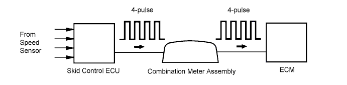
The speed sensor for skid control ECU detects the wheel speed and sends the appropriate signals to the skid control ECU.
The ECM converts these signals into a 4-pulse signal and outputs it to the combination meter.
After this signal is converted into a more precise rectangular waveform by the waveform shaping circuit inside the combination meter, it is then transmitted to the ECM. The ECM determines the vehicle speed based on the frequency of these pulse signals.
| DTC No. | DTC Detection Condition | Trouble Area |
|---|---|---|
| 42 | All conditions below are detected continuously for 8 sec. or more:
|
|
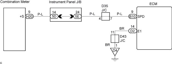
WIRING DIAGRAM
INSPECTION PROCEDURE
PROCEDURE
-
CHECK OPERATION OF SPEEDOMETER
-
Drive the vehicle and check if the operation of the speedometer in the combination meter is normal.
OK The speedometer operates normally according to vehicle speed. Tech Tips
The vehicle speed sensor is operating normally if the speedometer display is normal.
NG 
CHECK SPEEDOMETER CIRCUIT
OK 
-
-
INSPECT ECM (CHECK VOLTAGE)
-
Shift the shift lever to the neutral position.
-
Jack up the vehicle.
-
Turn the ignition switch ON.
-
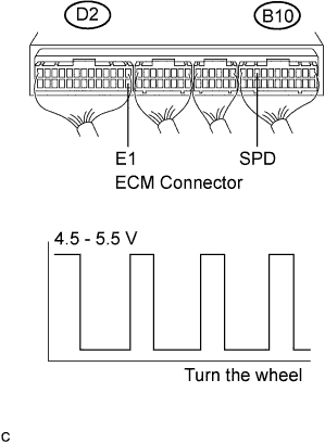
Measure the voltage between the terminals SPD and E1 of the ECM connector when the wheel is turned slowly.
OK Tester Connection Specified Condition SPD (B10-9) - E1 (D2-14) Correct waveform shown
NG 
CHECK HARNESS AND CONNECTOR (COMBINATION METER - ECM) Click here
OK 
REPLACE ECM
-
-
CHECK HARNESS AND CONNECTOR (COMBINATION METER - ECM)
-
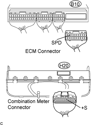
Disconnect the combination meter connector.
-
Disconnect the ECM B10 connector.
-
Measure the resistance according to the value(s) in the table below.
Standard resistance (Check for open) Tester Connection Specified Condition +S (H20-9) - SPD (B10-9) Below 1 Ω Standard resistance (Check for short) Tester Connection Specified Condition SPD (B10-9) - Body ground 10 kΩ or higher
NG
REPAIR OR REPLACE HARNESS OR CONNECTOR
OK
REPLACE ECM
-