СИСТЕМА ECD, Diagnostic DTC:39
| DTC Code | DTC Name |
|---|---|
| 39 | Fuel Temperature Sensor Circuit Malfunction |
DESCRIPTION
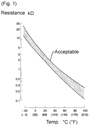
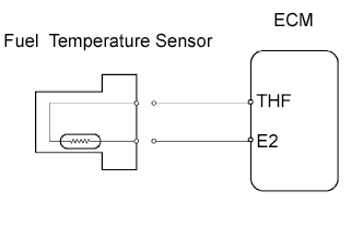
The fuel temperature sensor senses the fuel temperature. A thermistor built into the sensor changes the resistance value according to the fuel temperature. The lower the fuel temperature, the greater the thermistor resistance value, and the higher the fuel temperature, the lower the thermistor resistance value (See Fig. 1).
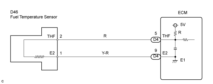
The fuel temperature sensor is connected to the ECM. The 5 V power source voltage in the ECM is applied to the fuel temperature sensor from terminal THF via a resistor R. That is, resistor R and the fuel temperature sensor are connected in series. When the resistance value of the fuel temperature sensor changes in accordance with changes in the fuel temperature, the potential at the terminal THF also changes. Based on this signal, the ECM increases the fuel injection volume to improve driveability during low engine revolution and high fuel temperature.
| DTC No. | DTC Detection Condition | Trouble Area |
|---|---|---|
| 39 | Open or short in fuel temperature sensor circuit for 0.5 sec. or more |
|
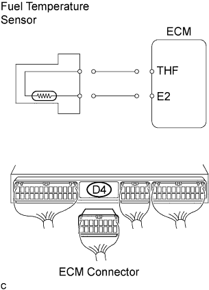
WIRING DIAGRAM
INSPECTION PROCEDURE
Tech Tips
-
If different DTCs that are related to different systems are output simultaneously while terminal E2 is used as a ground terminal, terminal E2 may be open.
-
Read freeze frame data using the intelligent tester. The ECM records vehicle and driving condition information as freeze frame data the moment a DTC is stored. When troubleshooting, freeze frame data can be helpful in determining whether the vehicle was running or stopped, whether the engine was warmed up or not, whether the air/fuel ratio was lean or rich, as well as other data recorded at the time of a malfunction.
When using intelligent tester:
PROCEDURE
-
READ VALUE USING INTELLIGENT TESTER (FUEL TEMPERATURE)
-
Connect the intelligent tester to the DLC3.
-
Turn the ignition switch ON.
-
Select the item "Powertrain/Engine and ECT/Data List/Fuel Temp" and read its value displayed on the intelligent tester.
Result Display Proceed - 40°C (- 40°F) A 140°C (284°F) or more B The same as actual fuel temperature C Tech Tips
When DTC 39 is present, check the fuel temperature by selecting "Powertrain/Engine and ECT/Data List/ Fuel Temp" on the intelligent tester.
Temperature displayed Malfunction - 40°C (- 40°F) Open circuit 140°C (284°F) or more Short circuit
B : 
CHECK HARNESS AND CONNECTOR (CHECK FOR SHORT) Click here
C :ПРОВЕРЬТЕ, НЕТ ЛИ ЭПИЗОДИЧЕСКИХ НЕИСПРАВНОСТЕЙ 
ПРОВЕРЬТЕ, НЕТ ЛИ ЭПИЗОДИЧЕСКИХ НЕИСПРАВНОСТЕЙ
A : 
-
-
CHECK HARNESS AND CONNECTOR (CHECK FOR OPEN)
-
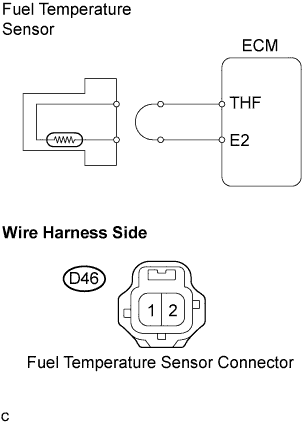
Disconnect the fuel temperature sensor connector.
-
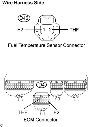
Connect the sensor terminals 1 and 2 of fuel temperature sensor harness side connector.
-
Turn the ignition switch ON.
-
Read the temperature value on the intelligent tester.
Temperature 140°C (284°F) or more
NG :
INSPECT ECM (CHECK FOR OPEN) Click here
OK :REPLACE FUEL TEMPERATURE SENSOR 
REPLACE FUEL TEMPERATURE SENSOR
-
-
INSPECT ECM (CHECK FOR OPEN)
-
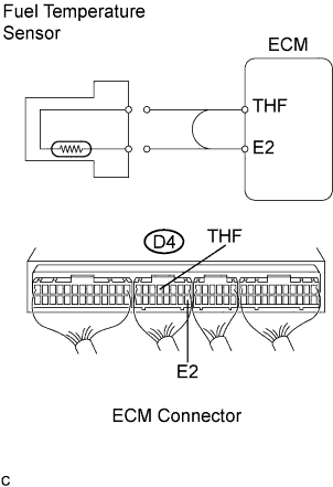
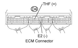
Connect terminals THF and E2 of the ECM connector.
-
Turn the ignition switch ON.
-
Read the temperature value on the intelligent tester.
Temperature 140°C (284°F) or more
NG :REPLACE ECM
REPLACE ECM
OK :REPAIR OR REPLACE HARNESS OR CONNECTOR
REPAIR OR REPLACE HARNESS OR CONNECTOR
-
-
CHECK HARNESS AND CONNECTOR (CHECK FOR SHORT)
-
Disconnect the fuel temperature sensor connector.
-
Turn the ignition switch ON.
-
Read the temperature value on the intelligent tester.
Temperature -40°C (-40°F) or more
NG :
INSPECT ECM (CHECK FOR SHORT) Click here
OK :REPLACE FUEL TEMPERATURE SENSOR
REPLACE FUEL TEMPERATURE SENSOR
-
-
INSPECT ECM (CHECK FOR SHORT)
-
Disconnect the ECM D4 connector.
-
Turn the ignition switch ON.
-
Read the temperature value on the intelligent tester.
Temperature -40°C (-40°F)
NG :REPLACE ECM
REPLACE ECM
OK :REPAIR OR REPLACE HARNESS OR CONNECTOR
REPAIR OR REPLACE HARNESS OR CONNECTOR
-
When not using intelligent tester:
PROCEDURE
-
INSPECT ECM
-
Turn the ignition switch ON.
-
Measure the voltage according to the value(s) in the table below.
Standard voltage Tester Connection Specified Condition THF (D4-5) - E2 (D4-9) 0.2 to 3.8 V (20°C (68°F)) THF (D4-5) - E2 (D4-9) 0.1 to 1.5 V (80°C (176°F))
NG :
INSPECT FUEL TEMPERATURE SENSOR Click here
OK :ПРОВЕРЬТЕ, НЕТ ЛИ ЭПИЗОДИЧЕСКИХ НЕИСПРАВНОСТЕЙ
ПРОВЕРЬТЕ, НЕТ ЛИ ЭПИЗОДИЧЕСКИХ НЕИСПРАВНОСТЕЙ
-
-
INSPECT FUEL TEMPERATURE SENSOR
-
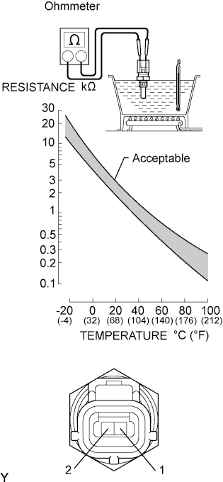
Measure the resistance according to the illustration.
OK The resistance value is within the acceptable range shown in the illustration. Note
In case of checking the fuel temperature sensor in the water, do not allow water top to enter the terminals, and after checking, wipe out the sensor.
NG :REPLACE FUEL TEMPERATURE SENSOR
REPLACE FUEL TEMPERATURE SENSOR
OK :
-
-
CHECK HARNESS AND CONNECTOR (ECM - FUEL TEMPERATURE SENSOR)
-
Disconnect the fuel temperature sensor connector.
-
Disconnect the ECM D4 connector.
-
Measure the resistance according to the value(s) in the table below.
Standard resistance (Check for open) Tester Connection Specified Condition THF (D46-2) - THF (D4-5) Below 1 Ω E2 (D46-1) - E2 (D4-9) Below 1 Ω Standard resistance (Check for short) Tester Connection Specified Condition THF (D4-5) - E2 (D4-9) 10 kΩ or higher
NG :REPAIR OR REPLACE HARNESS OR CONNECTOR
REPAIR OR REPLACE HARNESS OR CONNECTOR
OK :REPLACE ECM
REPLACE ECM
-