СИСТЕМА ECD, Diagnostic DTC:19 (1)
| DTC Code | DTC Name |
|---|---|
| 19 (1) | Accelerator Position Sensor Circuit Malfunction |
DESCRIPTION
Tech Tips
-
This is repair procedure of "accelerator pedal position sensor".
-
This electrical throttle system does not use a throttle cable.
-
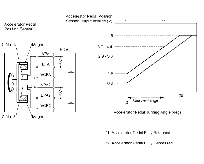
This accelerator pedal position sensor is non-contact type.
The accelerator pedal position sensor is mounted in the accelerator pedal to detect the opening angle of the accelerator pedal. Since this sensor is electronically controlled with hall elements, accurate control and reliability can be obtained. It has the 2 sensors to detect the accelerator position and a malfunction of the accelerator position sensor.
In the accelerator pedal position sensor, the voltage applied to pedal terminals VPA and VPA2 of the ECM changes between 0 V and 5 V, in proportion to the opening angle of the accelerator pedal. The VPA is a signal to indicate the actual accelerator pedal opening angle which is used for the engine control, and the VPA2 is a signal to indicate the information about the opening angle which is used for detecting a malfunction. The ECM judges the current opening angle of the accelerator pedal from these signals input from terminals VPA and VPA2, and the ECM controls the injection pump based on these signals.
| DTC No. | DTC Detecting Condition | Trouble Area |
|---|---|---|
| 19(1) | Condition (a), (b), (c) or (d) continues for 2.0 seconds: (a) VPA <= 0.2 V and VPA2 <= 0.5 V (b) VPA >= 4.8 V (c) When 3.45 V >= VPA >= 0.2 V, and VPA2 >= 4.8 V (d) VPA-VPA2 <= 0.02 V |
|
| Condition (a) continues for 0.5 seconds: (a) VPA <= 0.2 V or VPA2 <= 0.5 V |
Tech Tips
After confirming DTC 19(1), use the intelligent tester to confirm the throttle valve opening percentage.
| Trouble area | Accelerator pedal position expressed as voltage | |||
|---|---|---|---|---|
| Accelerator pedal released | Accelerator pedal depressed | |||
| ACCEL POS #1 | ACCEL POS #2 | ACCEL POS #1 | ACCEL POS #2 | |
| VC circuit open | 0 - 0.2 V | 0 - 0.2 V | 0 - 0.2 V | 0 - 0.2 V |
| VPA circuit open or ground short | 0 - 0.2 V | 1.2 - 2.0 V | 0 - 0.2 V | 3.4 - 5.3 V |
| VPA2 circuit open or ground short | 0.5 - 1.1 V | 0 - 0.2 V | 2.6 - 4.5 V | 0 - 0.2 V |
| E2 circuit open | 4.5 - 5.5 V | 4.5 - 5.5 V | 4.5 - 5.5 V | 4.5 - 5.5 V |
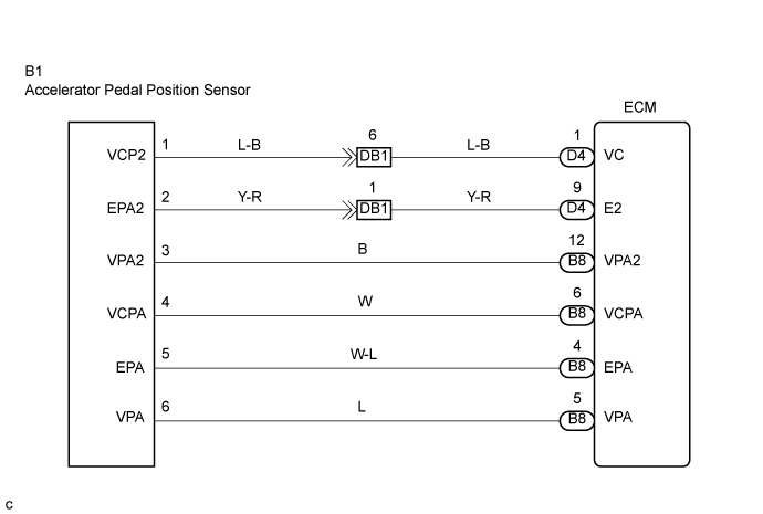
WIRING DIAGRAM
INSPECTION PROCEDURE
Tech Tips
Read freeze frame data using the intelligent tester. The ECM records vehicle and driving condition information as freeze frame data the moment a DTC is stored. When troubleshooting, freeze frame data can be helpful in determining whether the vehicle was running or stopped, whether the engine was warmed up or not, whether the air/fuel ratio was lean or rich, as well as other data recorded at the time of a malfunction.
When using intelligent tester:
PROCEDURE
-
READ VALUE USING INTELLIGENT TESTER (ACCELERATOR POSITION)
-
Connect the intelligent tester to the DLC3.
-
Turn the ignition switch ON.
-
Select the item "Powertrain/Engine and ECT/Data List/Accel position" and read its value displayed on the intelligent tester.
OK Check that the value displayed on the intelligent tester changes by repeatedly depressing and releasing the accelerator pedal.
NG 
CHECK HARNESS AND CONNECTOR (ECM - ACCELERATOR PEDAL POSITION SENSOR) Click here
OK 
-
-
READ OUTPUT DTC (ACCELERATOR PEDAL POSITION SENSOR DTC IS OUTPUT AGAIN)
-
Clear the DTC Click here.
-
Start the engine.
-
Idle the engine for 15 sec. or more.
-
Read the DTC Click here.
Result Display (DTC output) Proceed to DTC 19(1) is output again A No DTC output B
B 
SYSTEM OK
A 
REPLACE ECM
-
-
CHECK HARNESS AND CONNECTOR (ECM - ACCELERATOR PEDAL POSITION SENSOR)
-
Disconnect the accelerator pedal position sensor connector.
-
Disconnect the ECM B8 and D4 connectors.
-
Measure the resistance according to the value(s) in the table below.
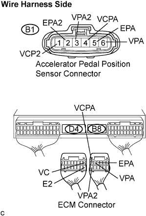
Standard resistance (Check for open) Tester Connection Specified Condition VCP2 (B1-1) - VC (D4-1) Below 1 Ω EPA2 (B1-2) - E2 (D4-9) Below 1 Ω VPA2 (B1-3) - VPA2 (B8-12) Below 1 Ω VCPA (B1-4) - VCPA (B8-6) Below 1 Ω EPA (B1-5) - EPA (B8-4) Below 1 Ω VPA (B1-6) - VPA (B8-5) Below 1 Ω Standard resistance (Check for short) Tester Connection Specified Condition VCP2 (B1-1) or VC (D4-1) - Body ground 10 kΩ or higher EPA2 (B1-2) or E2 (D4-9) - Body ground 10 kΩ or higher VPA2 (B1-3) or VPA2 (B8-12) - Body ground 10 kΩ or higher VCPA (B1-4) or VCPA (B8-6) - Body ground 10 kΩ or higher EPA (B1-5) or EPA (B8-4) - Body ground 10 kΩ or higher VPA (B1-6) or VPA (B8-5) - Body ground 10 kΩ or higher
NG
REPAIR OR REPLACE HARNESS OR CONNECTOR
OK
-
-
INSPECT ECM (VC AND VCPA VOLTAGE)
-
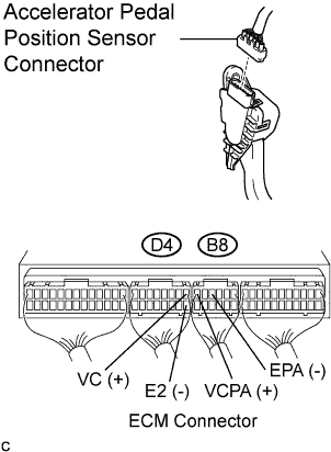
Disconnect the accelerator pedal position sensor connector.
-
Turn the ignition switch ON.
-
Measure the voltage according to the value(s) in the table below.
Standard voltage Tester Connection Specified Condition VC (D4-1) - E2 (D4-9) 4.5 to 5.5 V VCPA (B8-6) - EPA (B8-4) 4.5 to 5.5 V
NG
REPLACE ECM
OK
-
-
REPLACE ACCELERATOR PEDAL ROD ASSEMBLY
NEXT
-
READ OUTPUT DTC (ACCELERATOR PEDAL POSITION SENSOR DTC IS OUTPUT AGAIN)
-
Clear the DTC Click here.
-
Start the engine.
-
Idle the engine for 15 sec. or more.
-
Read the DTC Click here.
Result Display (DTC output) Proceed to DTC 19(1) is output again A No DTC output B
NG
SYSTEM OK
A
REPLACE ECM
-
When not using intelligent tester:
PROCEDURE
-
CHECK HARNESS AND CONNECTOR (ECM - ACCELERATOR PEDAL POSITION SENSOR)
-
Disconnect the accelerator pedal position sensor connector.
-
Disconnect the ECM B8 and D4 connectors.
-
Measure the resistance according to the value(s) in the table below.
Standard resistance (Check for open) Tester Connection Specified Condition VCP2 (B1-1) - VC (D4-1) Below 1 Ω EPA2 (B1-2) - E2 (D4-9) Below 1 Ω VPA2 (B1-3) - VPA2 (B8-12) Below 1 Ω VCPA (B1-4) - VCPA (B8-6) Below 1 Ω EPA (B1-5) - EPA (B8-4) Below 1 Ω VPA (B1-6) - VPA (B8-5) Below 1 Ω Standard resistance (Check for short) Tester Connection Specified Condition VCP2 (B1-1) or VC (D4-1) - Body ground 10 kΩ or higher EPA2 (B1-2) or E2 (D4-9) - Body ground 10 kΩ or higher VPA2 (B1-3) or VPA2 (B8-12) - Body ground 10 kΩ or higher VCPA (B1-4) or VCPA (B8-6) - Body ground 10 kΩ or higher EPA (B1-5) or EPA (B8-4) - Body ground 10 kΩ or higher VPA (B1-6) or VPA (B8-5) - Body ground 10 kΩ or higher
NG
REPAIR OR REPLACE HARNESS OR CONNECTOR
OK
-
-
INSPECT ECM (VC AND VCPA VOLTAGE)
-
Disconnect the accelerator pedal position sensor connector.
-
Turn the ignition switch ON.
-
Measure the voltage according to the value(s) in the table below.
Standard voltage Tester Connection Specified Condition VC (D4-1) - E2 (D4-9) 4.5 to 5.5 V VCPA (B8-6) - EPA (B8-4) 4.5 to 5.5 V
NG
REPLACE ECM
OK
-
-
REPLACE ACCELERATOR PEDAL ROD ASSEMBLY
NEXT
-
READ OUTPUT DTC (ACCELERATOR PEDAL POSITION SENSOR DTC IS OUTPUT AGAIN)
-
Clear the DTC Click here.
-
Start the engine.
-
Idle the engine for 15 sec. or more.
-
Read the DTC Click here.
Result Display (DTC output) Proceed to DTC 19(1) is output again A No DTC output B
B
SYSTEM OK
A
REPLACE ECM
-