ИНТЕГРИРОВАННОЕ РЕЛЕ ПРОВЕРКА
-
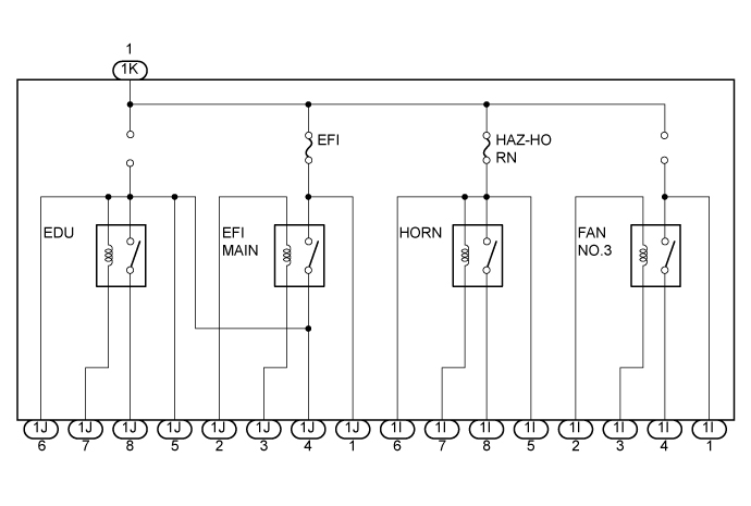
INSPECT INTEGRATION NO.1 RELAY
-
Measure the resistance of the fan No.3 relay.
-
Using an ohmmeter, measure the resistance according to the values in the table below.
Standard resistance Tester Connection Specified Condition 1I-2 ←→ 1I-3 Approx 310 Ω 1I-1 ←→ 1I-4 10 kΩ or higher -
Connect the battery positive (+) lead to terminal 1I-2 and the negative (-) lead to terminal 1I-3. Using an ohmmeter, measure the resistance according to the value in the table below.
Standard resistance Tester Connection Specified Condition 1I-1 ←→ 1I-4 Below 1 Ω
(When battery voltage is applied to terminals 1I-2 and 1I-3)
If the resistance is not as specified, replace the integration relay.
-
-
Measure the resistance of the HORN relay.
-
Using an ohmmeter, measure the resistance according to the value in the table below.
Standard resistance Tester Connection Specified Condition 1I-5 ←→ 1I-7 Approx 310 Ω If the resistance is not as specified, replace the integration relay.
-
-
Measure the voltage of the HORN relay.
-
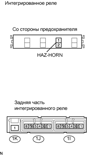
Disconnect the HAZ-HORN fuse. Connect the battery positive (+) lead to terminal HAZ-HORN fuse 2 (+). Using a voltmeter, measure the voltage according to the values in the table below.
Note
While using the battery for inspection, do not bring the positive and negative tester probes too close to each other as a short circuit may occur.
Standard voltage Tester Connection Specified Condition 1I-5 ←→ negative battery terminal (-) battery voltage 1I-8 (+) ←→ negative battery terminal (-) 0 V If the voltage is not as specified, replace the integration relay.
-
Connect the battery positive (+) lead to terminal HAZ-HORN fuse 2 (+) and negative (-) lead to terminal 1I-7.Using a voltmeter, measure the voltage according to the value in the table below.
Note
While using the battery for inspection, do not bring the positive and negative tester probes too close to each other as a short circuit may occur.
Standard voltage Tester Connection Specified Condition 1I-8 (+) ←→ negative battery terminal (-) battery voltage
(When battery voltage is applied to terminals HAZ-HORN fuse 2 (+) and 1I-7)
If the voltage is not as specified, replace the integration relay.
-
-
Measure the resistance of the EFI MAIN relay.
-
Using an ohmmeter, measure the resistance according to the values in the table below.
Standard resistance Tester Connection Specified Condition 1J-2 ←→ 1J-3 Approx 310 Ω 1J-1 ←→ 1J-4 10 kΩ or higher -
Connect the battery positive (+) lead to terminal 1J-2 and negative (-) lead to terminal 1J-3. Using an ohmmeter, measure the resistance according to the value in the table below.
Standard resistance Tester Connection Specified Condition 1J-1 ←→ 1J-4 Below 1 Ω
(When battery voltage is applied to terminals 1J-2 and 1J-3)
If the resistance is not as specified, replace the integration relay.
-
-
Measure the resistance of the EDU relay.
-
Using an ohmmeter, measure the resistance according to the value in the table below.
Standard resistance Tester Connection Specified Condition 1J-4 ←→ 1J-7 Approx 310 Ω If the resistance is not as specified, replace the integration relay.
-
-
Measure the voltage of the EDU relay.
-
Connect the battery positive (+) lead to terminal 1J-4.Using a voltmeter, measure the voltage according to the values in the table below.
Note
While using the battery for inspection, do not bring the positive and negative tester probes too close to each other as a short circuit may occur.
Standard voltage Tester Connection Specified Condition 1J-5 (+) ←→ negative battery terminal (-) battery voltage 1J-8 (+) ←→ negative battery terminal (-) 0 V If the voltage is not as specified, replace the integration relay.
-
Connect the battery positive (+) lead to terminal 1J-4 and battery negative (-) lead to terminal 1J-7.Using a voltmeter, measure the voltage according to the value in the table below.
Note
While using the battery for inspection, do not bring the positive and negative tester probes too close to each other as a short circuit may occur.
Standard voltage Tester Connection Specified Condition 1J-8 (+) ←→ negative battery terminal (-) battery voltage
(When battery voltage is applied to terminals 1J-4 and 1J-7)
If the voltage is not as specified, replace the integration relay.
-
-