СИСТЕМА ECD Pre-heating Control Circuit
DESCRIPTION
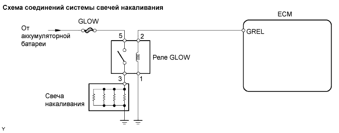
The glow plug is mounted inside the engine combustion chamber. To ensure efficient engine starting with a cold engine, the ECM calculates a time interval of the current that needs to flow through the glow plug depending on the starting engine coolant temperature when the ignition switch is turned ON. The ECM then turns on the GLOW relay and permits the current to flow through the glow plug based on the ECM's calculated time. The GLOW relay is then heated, and enhances fuel combustion with a cold engine.
This DTC will be set if the glow plug or the circuit is open.
Tech Tips
-
These troubleshooting procedures are for: 1) difficult starting engine in cold weather, and 2) difficulty driving/ vehicle malfunctions in cold weather immediately after engine is started.
-
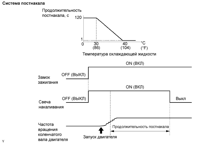
After the engine is started, the ECM performs an "after-glow" for a certain period of time. In proportion to the actual engine coolant temperature, the time period varies. The after-glow reduces diesel engine knocking, white smoke emissions and engine noises when the engine is cold.
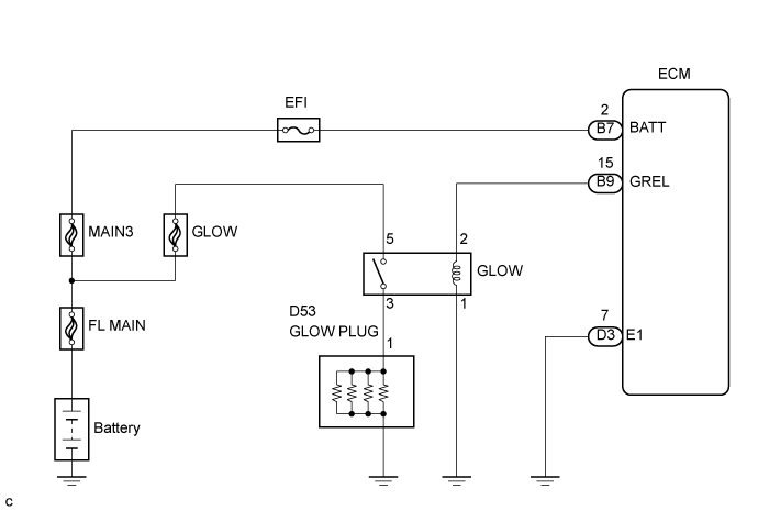
WIRING DIAGRAM
INSPECTION PROCEDURE
Note
After replacing the ECM, the new ECM needs registration Click here and initialization Click here.
PROCEDURE
-
INSPECT GLOW RELAY
-
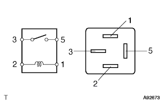
Remove the GLOW relay from the engine room R/B.
-
Measure the resistance of the relay.
Standard resistance Tester Connection Specified Condition 3 - 5 10 kΩ or higher 3 - 5 Below 1 Ω
(when battery voltage is applied to terminals 1 and 2)
NG 
REPLACE GLOW RELAY
OK 
-
-
INSPECT GLOW FUSE
-
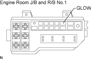
Remove the GLOW fuse from the engine room J/B and R/B No.1.
-
Measure the resistance of the fuse.
Standard resistance Below 1 Ω
NG
CHECK FOR SHORT IN ALL HARNESS AND COMPONENTS CONNECTED TO FUSE, AND REPLACE FUSE
OK
-
-
INSPECT GLOW PLUG ASSEMBLY (RESISTANCE)
-
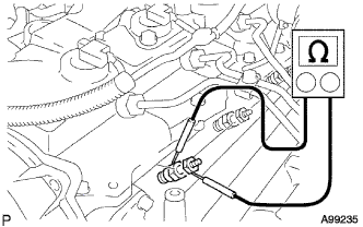
Disconnect the glow plug wire.
-
Measure the resistance of the glow plugs.
Standard resistance Tester Connection Condition Specified Condition Glow plug terminal - Body ground 20°C (68°F) Approximately 0.95 Ω Tech Tips
If any of the glow plugs has an open malfunction, the engine power is insufficient only when the engine is cold.
Note
-
Exercise extreme care not to damage the glow plug pipes. Damaging them could cause an open circuit, or shorten the life of the glow plugs.
-
Keep the glow plugs free of oil and fuel while cleaning.
-
Wipe any oil off of the terminal and Bakelite washer with a clean, dry cloth during inspection.
-
Do not apply more than 11 V to the glow plugs as it may cause an open circuit.
-
NG
REPLACE GLOW PLUG ASSEMBLY
OK
-
-
CHECK GLOW PLUG ASSEMBLY (INSTALLATION)
-
Check the glow plug installation.
OK Glow plugs are installed securely. - Torque:
- 13 N*m { 130 kgf*cm, 10 ft.*lbf }
NG
TIGHTEN GLOW PLUG
OK
-
-
CHECK HARNESS AND CONNECTOR (GLOW RELAY - ECM, GLOW RELAY - BODY GROUND)
-
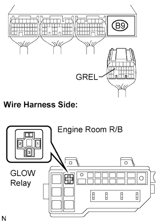
Disconnect the B9 ECM connector.
-
Remove the GLOW relay from the engine room R/B.
-
Measure the resistance of the wire harness side connectors.
Standard resistance Tester Connection Specified Condition B9-15 (GREL) - R/B GLOW relay terminal 2 Below 1 Ω R/B GLOW relay terminal 1 - Body ground Below 1 Ω B9-15 (GREL) - Body ground 10 kΩ or higher
NG
REPAIR OR REPLACE HARNESS AND CONNECTOR
OK
-
-
CHECK HARNESS AND CONNECTOR (GLOW PLUG - GLOW RELAY, BATTERY - GLOW RELAY)
-
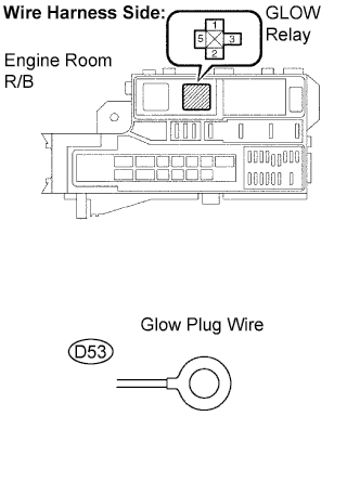
Remove the GLOW relay from the engine room R/B.
-
Disconnect the D53 glow plug connector.
-
Measure the resistance of the wire harness side connectors.
Standard resistance Tester Connection Specified Condition R/B GLOW relay terminal 3 - Glow plug wire connector Below 1 Ω R/B GLOW relay terminal 5 - Positive (+) battery terminal cabled Below 1 Ω
NG
REPAIR OR REPLACE HARNESS AND CONNECTOR
OK
-
-
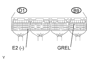
CHECK ECM TERMINAL VOLTAGE (GREL TERMINAL)
-
Start the engine.
-
Measure the voltage of the ECM connectors.
Standard voltage Tester Connection Condition Specified Condition B9-15 (GREL) - D1-28 (E2) Engine coolant temperature 40°C (104°F) or less 9 to 14 V
NG
REPLACE ECM
OK
-
-
CHECK ECM TERMINAL VOLTAGE (BATT TERMINAL)
-
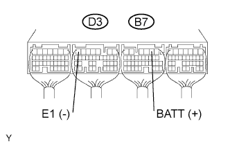
Measure the voltage of the ECM connectors.
Standard voltage Tester Connection Specified Condition B7-2 (BATT) - D3-7 (E1) 9 to 14 V
NG
REPAIR OR REPLACE HARNESS AND CONNECTOR
OK 
CHECK FOR INTERMITTENT PROBLEMS
-