СИСТЕМА ECD, Diagnostic DTC:P2120/19, P2122/19, P2123/19, P2125/19, P2127/19, P2128/19, P2138/19
| DTC Code | DTC Name |
|---|---|
| P2120/19 | Throttle / Pedal Position Sensor / Switch "D" Circuit |
| P2122/19 | Throttle / Pedal Position Sensor / Switch "D" Circuit Low Input |
| P2123/19 | Throttle / Pedal Position Sensor / Switch "D" Circuit High Input |
| P2125/19 | Throttle / Pedal Position Sensor / Switch "E" Circuit |
| P2127/19 | Throttle / Pedal Position Sensor / Switch "E" Circuit Low Input |
| P2128/19 | Throttle / Pedal Position Sensor / Switch "E" Circuit High Input |
| P2138/19 | Throttle / Pedal Position Sensor / Switch "D" / "E" Voltage Correlation |
DESCRIPTION
Tech Tips
-
This is the repair procedure for the accelerator pedal position sensor.
-
This electrical throttle system does not use a throttle cable.
-
This accelerator pedal position sensor is a non-contact type.
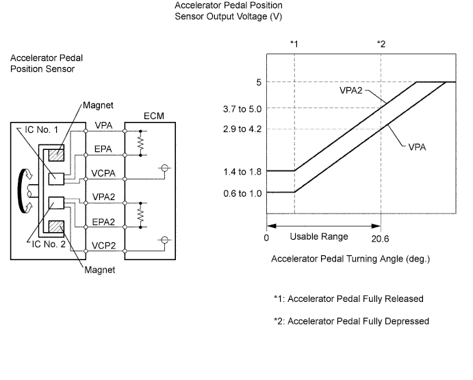
The accelerator pedal position sensor is mounted on the accelerator pedal and detects the opening angle of the accelerator pedal. Since this sensor is electronically controlled with Hall-effect elements, accurate control and reliability can be obtained. It has 2 sensors to detect the accelerator position and a malfunction of the accelerator position sensor.
In the accelerator pedal position sensor, the voltage applied to pedal terminals VPA and VPA2 of the ECM changes between 0 V and 5 V in proportion to the opening angle of the accelerator pedal. The VPA is a signal to indicate the actual accelerator pedal opening angle which is used for the engine control, and the VPA2 is a signal to indicate the information about the opening angle which is used for detecting malfunctions. The ECM judges the current opening angle of the accelerator pedal using signals from terminals VPA and VPA2, and the ECM controls the throttle motor based on these signals.
| DTC No. | DTC Detection Condition (All of following are 1 trip detection logic) |
Trouble Area |
|---|---|---|
| P2120/19 |
|
|
| P2122/19 | VPA is 0.2 V or less for 0.5 sec. or more when VPA2 output indicate accelerator pedal is opened |
|
| P2123/19 |
|
|
| P2125/19 |
|
|
| P2127/19 | VPA2 is 0.5 V or less for 0.5 sec. or more when VPA output indicates accelerator pedal is opened |
|
| P2128/19 |
|
|
| P2138/19 |
|
|
Tech Tips
When DTC P2120/19, P2122/19, P2123/19, P2125/19, P2127/19, P2128/19 or P2138/19 is detected, check the output voltage of the accelerator pedal position sensor by entering the following menus on the intelligent tester : Powertrain / Engine / Data List / Accel Position 1 and Accel Position 2.
| - | Accelerator pedal position expressed as voltage output | Accelerator pedal position expressed as voltage output | Accelerator pedal position expressed as voltage output | Accelerator pedal position expressed as voltage output |
| - | Accelerator pedal released | Accelerator pedal released | Accelerator pedal depressed | Accelerator pedal depressed |
| Trouble Area | Accelerator Position 1 | Accelerator Position 2 | Accelerator Position 1 | Accelerator Position 2 |
| VCP circuit open | 0 to 0.2 V | 0 to 0.2 V | 0 to 0.2 V | 0 to 0.2 V |
| VPA circuit open or ground short | 0 to 0.2 V | 1.4 to 1.8 V | 0 to 0.2 V | 3.7 to 5.0 V |
| VPA2 circuit open or ground short | 0.6 to 1.0 V | 0 to 0.2 V | 2.9 to 4.2 V | 0 to 0.2 V |
| EP circuit open | 4.5 to 5.0 V | 4.5 to 5.0 V | 4.5 to 5.0 V | 4.5 to 5.0 V |
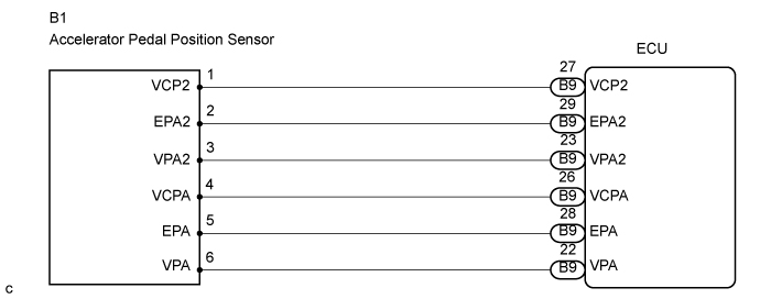
WIRING DIAGRAM
INSPECTION PROCEDURE
Note
After replacing the ECM, the new ECM needs registration Click here and initialization Click here.
Tech Tips
Read freeze frame data using the intelligent tester. The ECM records vehicle and driving condition information as freeze frame data the moment a DTC is stored. When troubleshooting, freeze frame data can help determine if the vehicle was running or stopped, if the engine was warmed up or not, and other data from the time the malfunction occurred.
When using intelligent tester:
PROCEDURE
-
READ VALUE USING ACCELERATOR PEDAL POSITION SENSOR
-

Connect the intelligent tester to the DLC3.
-
Turn the ignition switch ON and turn the intelligent tester ON.
-
Enter the following menus: Powertrain / Engine / Data List / Accel Position 1 and Accel Position 2.
-
Read the values.
Standard voltage Accelerator Pedal Accel Position 1 Accel Position 2 Released 0.5 to 1.1 V 1.2 to 2.0 V Depressed 2.6 to 4.5 V 3.4 to 5.0 V
OK 
CHECK IF OUTPUT DTC RECURS Click here
NG 
-
-
CHECK HARNESS AND CONNECTOR (ACCELERATOR PEDAL POSITION SENSOR - ECM)
-
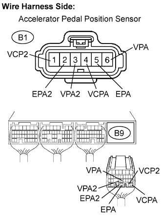
Disconnect the B1 sensor connector.
-
Disconnect the B9 ECM connector.
-
Measure the resistance of the wire harness side connectors.
Standard resistance Tester Connection Specified Condition B1-1 (VCP2) - B9-27 (VCP2) Below 1 Ω B1-2 (EPA2) - B9-29 (EPA2) Below 1 Ω B1-3 (VPA2) - B9-23 (VPA2) Below 1 Ω B1-4 (VCPA) - B9-26 (VCPA) Below 1 Ω B1-5 (EPA) - B9-28 (EPA) Below 1 Ω B1-6 (VPA) - B9-22 (VPA) Below 1 Ω B1-1 (VCP2) or B9-27 (VCP2) - Body ground 10 kΩ or higher B1-2 (EPA2) or B9-29 (EPA2) - Body ground 10 kΩ or higher B1-3 (VPA2) or B9-23 (VPA2) - Body ground 10 kΩ or higher B1-4 (VCPA) or B9-26 (VCPA) - Body ground 10 kΩ or higher B1-5 (EPA) or B9-28 (EPA) - Body ground 10 kΩ or higher B1-6 (VPA) or B9-22 (VPA) - Body ground 10 kΩ or higher
NG 
REPAIR OR REPLACE HARNESS AND CONNECTOR
OK
-
-
CHECK ECM TERMINAL VOLTAGE (VCPA AND VCP2 TERMINALS)
-
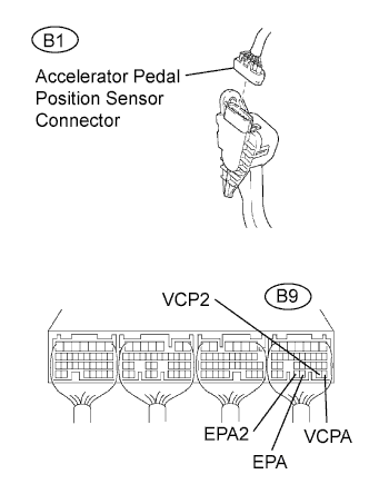
Disconnect the B1 sensor connector.
-
Turn the ignition switch ON.
-
Measure the voltage of the ECM connector.
Standard voltage Tester Connection Specified Condition B9-26 (VCPA) - B9-28 (EPA) 4.5 to 5.0 V B9-27 (VCP2) - B9-29 (EPA2) 4.5 to 5.0 V
NG
REPLACE ECM
OK
-
-
REPLACE ACCELERATOR PEDAL ROD ASSEMBLY
NEXT
-
CHECK IF OUTPUT DTC RECURS
-
Clear the DTC Click here.
-
Start the engine.
-
Drive the engine at idle for 15 seconds or more.
-
Read the DTC Click here.
Result Display (DTC output) Proceed to P2120/19, P2122/19, P2123/19, P2125/19, P2127/19, P2128/19 or P2138/19 is output again A P2120/19, P2122/19, P2123/19, P2125/19, P2127/19, P2128/19orP2138/19 is not output B
B
END
A 
REPLACE ECM
-
When not using intelligent tester:
PROCEDURE
-
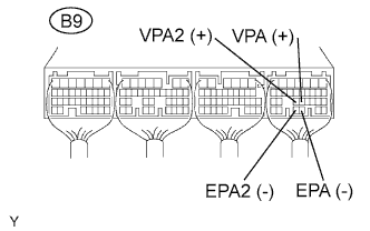
CHECK ECM TERMINAL VOLTAGE (VPA AND VPA2 TERMINALS)
-
Turn the ignition switch ON.
-
Measure the voltage of the ECM connector.
Standard voltage Tester Condition Accelerator Pedal Condition Specified Condition B9-22 (VPA) - B9-28 (EPA) Released 0.5 to 1.1 V B9-22 (VPA) - B9-28 (EPA) Depressed 2.6 to 4.5 V B9-23 (VPA2) - B9-29 (EPA2) Released 1.2 to 2.0 V B9-23 (VPA2) - B9-29 (EPA2) Depressed 3.4 to 5.0 V
OK
REPLACE ECM
NG
-
-
CHECK HARNESS AND CONNECTOR (ACCELERATOR PEDAL POSITION SENSOR - ECM)
-
Disconnect the B1 sensor connector.
-
Disconnect the B9 ECM connector.
-
Measure the resistance of the wire harness side connectors.
Standard resistance Tester Connection Specified Condition B1-1 (VCP2) - B9-27 (VCP2) Below 1 Ω B1-2 (EPA2) - B9-29 (EPA2) Below 1 Ω B1-3 (VPA2) - B9-23 (VPA2) Below 1 Ω B1-4 (VCPA) - B9-26 (VCPA) Below 1 Ω B1-5 (EPA) - B9-28 (EPA) Below 1 Ω B1-6 (VPA) - B9-22 (VPA) Below 1 Ω B1-1 (VCP2) or B9-27 (VCP2) - Body ground 10 kΩ or higher B1-2 (EPA2) or B9-29 (EPA2) - Body ground 10 kΩ or higher B1-3 (VPA2) or B9-23 (VPA2) - Body ground 10 kΩ or higher B1-4 (VCPA) or B9-26 (VCPA) - Body ground 10 kΩ or higher B1-5 (EPA) or B9-28 (EPA) - Body ground 10 kΩ or higher B1-6 (VPA) or B9-22 (VPA) - Body ground 10 kΩ or higher
NG
REPAIR OR REPLACE HARNESS AND CONNECTOR
OK
-
-
CHECK ECM TERMINAL VOLTAGE (VCPA AND VCP2 TERMINALS)
-
Disconnect the B1 sensor connector.
-
Turn the ignition switch ON.
-
Measure the voltage of the ECM connector.
Standard voltage Tester Connection Specified Condition B9-26 (VCPA) - B9-28 (EPA)
B9-27 (VCP2) - B9-29 (EPA2)
4.5 to 5.0 V
NG
REPLACE ECM
OK
-
-
REPLACE ACCELERATOR PEDAL ROD ASSEMBLY
NEXT
-
CHECK IF OUTPUT DTC RECURS
-
Clear the DTC Click here.
-
Start the engine.
-
Drive the engine at idle for 15 seconds or more.
-
Read the DTC Click here.
Result Display (DTC output) Proceed to P2120/19, P2122/19, P2123/19, P2125/19, P2127/19, P2128/19 or P2138/19 is output again A P2120/19, P2122/19, P2123/19, P2125/19, P2127/19, P2128/19orP2138/19 is not output B
B
END
A
REPLACE ECM
-