СИСТЕМА ECD, Diagnostic DTC:P0200/97
| DTC Code | DTC Name |
|---|---|
| P0200/97 | Injector Circuit / Open |
DESCRIPTION
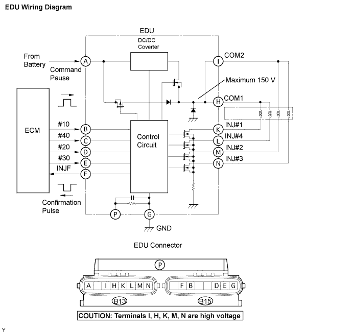
The EDU has been adopted to drive the injectors at high speeds. The EDU delivers high-speed driving under highly-pressurized fuel conditions using the DC/DC converter, which provides a high-voltage and quick- charging system.
Soon after the EDU receives an injection command (IJT) signal from the ECM, the EDU responds to the command with an injector injection confirmation (IJF) signal when the current is applied to the injector.
| DTC No. | DTC Detection Condition | Trouble Area |
|---|---|---|
| P0200/97 | Open or short in EDU or injector circuit After engine is started, there is no IJF signal from EDU to ECM, despite ECM sending IJT signal to EDU (1 trip detection logic) |
|
Tech Tips
DTC P0200/97 is detected when start the engine and let it idle for 30 seconds.
MONITOR DESCRIPTION
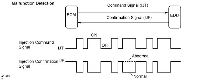
P0200/97 (Open or short in EDU or injector circuit):The ECM continuously monitors both injection command (IJT) signals and injection confirmation (IJF) signal. This DTC will be set if the ECM judges that the number of IJT signals and IJF signals are inconsistent.
The injectors are grounded over a Field Effect Transistor (FET) and a serial resistor. This resistor creates a voltage drop, which is monitored by the EDU (injector drive circuit), in relation to the current drawn by the injector. When the injector current becomes too high, the voltage drop over the resistor exceeds a specified level and no IJF signal for that cylinder is sent to the ECM.
P0200/97 refers to a malfunction in the EDU or injector circuit.
If this DTC is set, the ECM enters fail-safe mode and limits engine power. The fail-safe mode continues until the ignition switch is turned OFF.
MONITOR STRATEGY
| Required sensors | IJF signal from EDU |
| Frequency of operation | Continuous |
| Duration | 10 seconds |
| MIL operation | 1 driving cycle |
TYPICAL ENABLING CONDITIONS
| Item | Specification | Specification |
|---|---|---|
| Minimum | Maximum | |
| Engine speed | 500 rpm | - |
| Battery voltage | 11 V | - |
| Engine switch | ON | ON |
TYPICAL MALFUNCTION THRESHOLDS
| Threshold |
|---|
| The injection missing counter* for all the cylinders, or for one individual cylinder, reaches a specified number (taking approximately 1 second after starting the engine) *: Increments when no IJF signal is received from the EDU despite the ECM sending IJT signals |
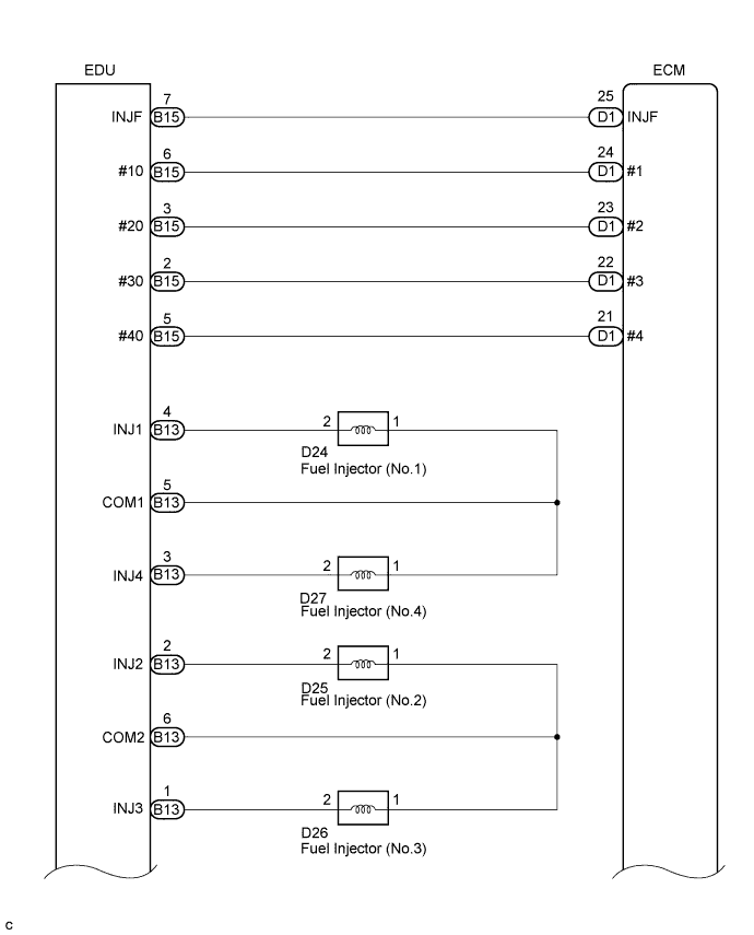
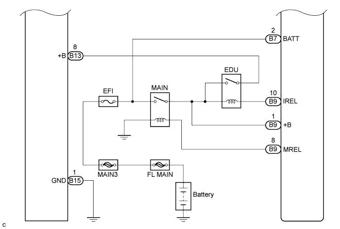
WIRING DIAGRAM
INSPECTION PROCEDURE
Note
-
After replacing the ECM, the new ECM needs registration Click here and initialization Click here.
-
After replacing the injector, the ECM needs registration Click here.
Tech Tips
Read freeze frame data using the intelligent tester. The ECM records vehicle and driving condition information as freeze frame data the moment a DTC is stored. When troubleshooting, freeze frame data can help determine if the vehicle was running or stopped, if the engine was warmed up or not, and other data from the time the malfunction occurred.
PROCEDURE
-
CHECK ENGINE CRANKING CONDITION
-
Check the engine cranking condition.
Result Result Proceed to Engine does not start*1 A Engine starts, but idling is rough*2 B Except above C Tech Tips
-
*1: Once DTC P0200 is cleared, it is not stored again even when the engine does not start due to a malfunction in the injector driver (EDU).
When the engine cannot be started due to a malfunction in the injector driver (EDU), the value for "Fuel Press" is higher than the value for "Target Common Rail Pressure"
-
*2: DTC P0200 is stored at this time.
-
B 
READ VALUE USING INTELLIGENT TESTER (INJECTION FEEDBACK VAL #1 to #4) Click here
C 
CHECK INTERMITTENT PROBLEMS
A 
-
-
CHECK ECM
-
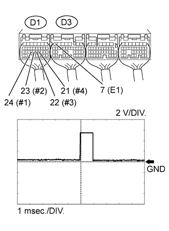
Check the waveform of the ECM connectors using an oscilloscope.
-
Check the waveform of the injector driver (EDU) connectors using an oscilloscope.
OK Tester Connection Condition Specified Condition D1-24 (#1) - D3-7 (E1) Cranking Correct waveform is as shown D1-23 (#2) - D3-7 (E1) Cranking Correct waveform is as shown D1-22 (#3) - D3-7 (E1) Cranking Correct waveform is as shown D1-21 (#4) - D3-7 (E1) Cranking Correct waveform is as shown
NG
REPLACE ECM Click here
OK
-
-
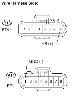
CHECK TERMINAL VOLTAGE INJECTOR DRIVER POWER SOURCE
-
Disconnect the injector driver connectors.
-
Measure the voltage according to the value(s) in the table below.
Standard voltage Tester Connection Switch Condition Specified Condition B13-8 (+B) - B15-1 (GND) Ignition switch ON 9 to 14 V -
Reconnect the injector driver connectors.
NG
REPAIR OR REPLACE HARNESS OR CONNECTOR Click here
OK
-
-
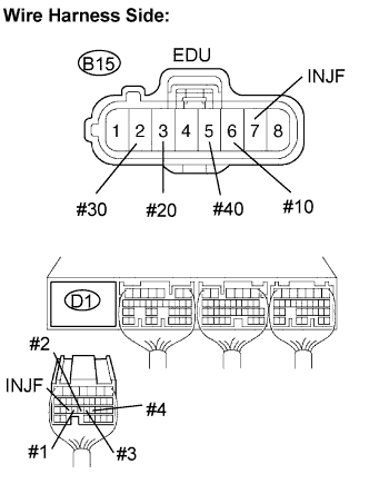
CHECK HARNESS AND CONNECTOR (INJECTOR DRIVER - ECM)
-
Disconnect the injector driver connector.
-
Disconnect the ECM connector.
-
Measure the resistance according to the value(s) in the table below.
Standard resistance Tester Connection Specified Condition B15-6 (#10) - D1-24 (#1) Below 1 Ω B15-3 (#20) - D1-23 (#2) Below 1 Ω B15-2 (#30) - D1-22 (#3) Below 1 Ω B15-5 (#40) - D1-21 (#4) Below 1 Ω B15-7 (INJF) - D1-25 (INJF) Below 1 Ω B15-6 (#10) or D1-24 (#1) - Body ground 10 kΩ or higher B15-3 (#20) or D1-23 (#2) - Body ground 10 kΩ or higher B15-2 (#30) or D1-22 (#3) - Body ground 10 kΩ or higher B15-5 (#40) or D1-21 (#4) - Body ground 10 kΩ or higher B15-7 (INJF) or D1-25 (INJF) - Body ground 10 kΩ or higher -
Reconnect the injector driver connector.
-
Reconnect the ECM connector.
NG
REPAIR OR REPLACE HARNESS OR CONNECTOR Click here
OK
-
-
REPLACE INJECTOR DRIVER
-
Replace the injector driver Click here.
NEXT
CONFIRM CONFIRM WHETHER MALFUNCTION HAS BEEN SUCCESSFULLY REPAIRED Click here
-
-
READ VALUE USING INTELLIGENT TESTER (INJECTION FEEDBACK VAL #1 to #4)
-
Connect the intelligent tester to the DLC3.
-
Turn the ignition switch to ON and turn the tester on.
-
Enter the following menus: Powertrain / Engine and ECT / Data List / Injection Feedback Val #1 to #4.
-
Start the engine.
-
Read the Injection Feedback Val #1 to #4 values while idling the engine.
Standard Value Item Engine Speed* Reference Value Injection Feedback Val #1 to #4 Idling +3.0 mm3/st or less
Tech Tips
-
*: The A/C switch and all accessory switches should be off, and the engine should be fully warmed up.
-
Fuel is not being injected in cylinders whose "Injection Feedback Val" is higher than 3 mm3/st. Inspection procedures beyond this point diagnose whether there are internal problems with fuel injectors, or whether there is a problem in the wiring of the fuel injector system.
-
NEXT
-
-
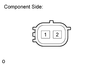
INSPECT INJECTOR ASSEMBLY (RESISTANCE)
-
Disconnect the fuel injector connectors.
-
Measure the resistance of the fuel injector
OK No open or short circuit malfunction. -
Reconnect the fuel injector connectors.
NG
REPLACE INJECTOR ASSEMBLY OF MALFUNCTIONING CYLINDER Click here
OK
-
-
INSPECT INJECTOR DRIVER
-
Disconnect the fuel injector connectors for all cylinders.
-
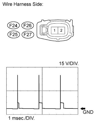
Check the waveform of the fuel injector connectors using an oscilloscope.
OK Tester Connection Condition Specified Condition F24-1 - F24-2 Cranking Voltage increases by 50 V or more F25-1 - F25-2 Cranking Voltage increases by 50 V or more F26-1 - F26-2 Cranking Voltage increases by 50 V or more F27-1 - F27-2 Cranking Voltage increases by 50 V or more
NG
CHECK HARNESS AND CONNECTOR (INJECTOR ASSEMBLY - INJECTOR DRIVER) Click here
OK
-
-
REPLACE INJECTOR ASSEMBLY OF MALFUNCTIONING CYLINDER
-
Replace the injector assembly Click here.
Note
-
When replacing the injector assembly for a cylinder, always be sure to use a new injection pipe.
-
Follow the procedure in the repair manual and temporarily install the injection pipes and nozzle leakage pipe, and then correctly position the injector assemblies. After that, tighten parts according to the torque specifications.
-
If the installation procedure is not performed correctly, injector assemblies may become out of position, which may cause the injector assemblies to deteriorate, resulting in malfunctions.
-
If an injector assembly deteriorates and malfunctions, other problems such as knocking, rough idle, etc. may occur.
-
If an injector assembly becomes out of position, it is possible that the seal between the injector assembly and injection pipe may become incomplete, resulting in a fuel leak.
-
NEXT
-
-
BLEED AIR FROM FUEL SYSTEM
-
Bleed the air from the fuel system Click here.
NEXT
-
-
REGISTER INJECTOR COMPENSATION CODE
-
Register the injector compensation code Click here.
NEXT
CONFIRM CONFIRM WHETHER MALFUNCTION HAS BEEN SUCCESSFULLY REPAIRED Click here
-
-
REPLACE ECM
-
Replace the ECM Click here.
NEXT
CONFIRM CONFIRM WHETHER MALFUNCTION HAS BEEN SUCCESSFULLY REPAIRED Click here
-
-
CHECK HARNESS AND CONNECTOR (INJECTOR ASSEMBLY - INJECTOR DRIVER)
-
Disconnect the injector assembly connectors.
-
Disconnect the injector driver connectors.
-
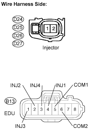
Measure the resistance according to the value(s) in the table below.
Standard resistance Tester Connection Specified Condition D24-2 - B13-4 (INJ1) Below 1 Ω D25-2 - B13-2 (INJ2) Below 1 Ω D26-2 - B13-1 (INJ3) Below 1 Ω D27-2 - B13-3 (INJ4) Below 1 Ω D24-1 - B13-5 (COM1) Below 1 Ω D25-1 - B13-6 (COM2) Below 1 Ω D26-1 - B13-6 (COM2) Below 1 Ω D27-1 - B13-5 (COM1) Below 1 Ω D24-2 or B13-4 (INJ1) - Body ground 10 kΩ or higher D25-2 or B13-2 (INJ2) - Body ground 10 kΩ or higher D26-2 or B13-1 (INJ3) - Body ground 10 kΩ or higher D27-2 or B13-3 (INJ4) - Body ground 10 kΩ or higher D24-1 or B13-5 (COM1) - Body ground 10 kΩ or higher D25-1 or B13-6 (COM2) - Body ground 10 kΩ or higher D26-1 or B13-6 (COM2) - Body ground 10 kΩ or higher D27-1 or B13-5 (COM1) - Body ground 10 kΩ or higher -
Reconnect the injector assembly connectors.
-
Reconnect the injector driver connectors.
NG
REPAIR OR REPLACE HARNESS OR CONNECTOR Click here
OK
-
-
REPLACE INJECTOR DRIVER
-
Replace the injector driver Click here.
NEXT
CONFIRM CONFIRM WHETHER MALFUNCTION HAS BEEN SUCCESSFULLY REPAIRED Click here
-
-
REPAIR OR REPLACE HARNESS OR CONNECTOR
-
Repair or replace the harness or connector.
NEXT
-
-
CONFIRM CONFIRM WHETHER MALFUNCTION HAS BEEN SUCCESSFULLY REPAIRED
-
Connect the intelligent tester to the DLC3.
-
Clear the DTCs Click here.
-
Turn the ignition switch off for 30 seconds or more.
-
Start the engine and idle it for 10 seconds.
-
Enter the following menus: Powertrain / Engine / DTC.
-
Confirm that the DTC is not output again.
NEXT 
END
-