СИСТЕМА ECD, Diagnostic DTC:P0105/31, P0107/35, P0108/35
| DTC Code | DTC Name |
|---|---|
| P0105/31 | Manifold Absolute Pressure / Barometric Pressure Circuit |
| P0107/35 | Manifold Absolute Pressure / Barometric Pressure Circuit Low Input |
| P0108/35 | Manifold Absolute Pressure / Barometric Pressure Circuit High Input |
DESCRIPTION
The manifold absolute pressure sensor detects the intake manifold pressure by using the built-in sensor unit. The ECM determines the basic injection duration and injection advance timing based on the voltage output by the manifold absolute pressure sensor.
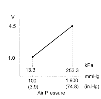
The manifold absolute pressure sensor monitors the absolute pressure inside the intake manifold (default is 0 kPa (0 mmHg, 0 in.Hg)). As a result the ECM controls the air-fuel ratio at the proper level under any driving conditions, and is not influenced by fluctuations in the atmospheric pressure due to factors such as high altitude, etc.
| DTC No. | DTC Detection Condition | Trouble Area |
|---|---|---|
| P0105/35 P0107/35 P0108/35 |
Open or short in manifold absolute pressure sensor circuit for 0.5 seconds or more (1 trip detection logic) |
|
Tech Tips
When DTC P0105/35, P0107/35 or P0108/35 is detected, check the intake manifold pressure by entering the following menus on the intelligent tester : Powertrain / Engine / Data List / MAP.
| Intake Manifold Pressure | Malfunction |
|---|---|
| Approximately 0 kPa | Short in PIM circuit |
| 250 kPa (1,875 mmHg, 73.8 in.Hg) or more |
|
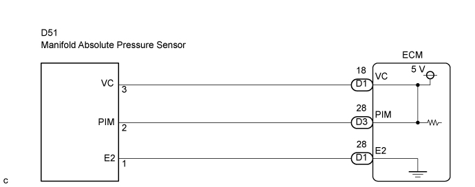
WIRING DIAGRAM
INSPECTION PROCEDURE
Note
After replacing the ECM, the new ECM needs registration Click here and initialization Click here.
Tech Tips
-
If DTCs related to different systems that have terminal E2 as the ground terminal are output simultaneously, terminal E2 may have an open circuit.
-
Read freeze frame data using the intelligent tester. The ECM records vehicle and driving condition information as freeze frame data the moment a DTC is stored. When troubleshooting, freeze frame data can help determine if the vehicle was running or stopped, if the engine was warmed up or not, and other data from the time the malfunction occurred.
When using intelligent tester:
PROCEDURE
-
READ VALUE USING MANIFOLD ABSOLUTE PRESSURE SENSOR
-
Connect the intelligent tester to the DLC3.
-
Turn the ignition switch ON and turn the intelligent tester ON.
-
Enter the following menus: Powertrain / Engine / Data List / MAP.
-
Read the values.
Standard Same value as the actual atmospheric pressure.
OK :ПРОВЕРЬТЕ, НЕТ ЛИ ЭПИЗОДИЧЕСКИХ НЕИСПРАВНОСТЕЙ 
ПРОВЕРЬТЕ, НЕТ ЛИ ЭПИЗОДИЧЕСКИХ НЕИСПРАВНОСТЕЙ
NG : 
-
-
CHECK ECM TERMINAL VOLTAGE (VC TERMINAL)
-
Turn the ignition switch ON.
-
Measure the voltage of the ECM connector.
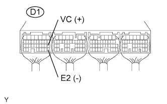
Standard voltage Tester Connection Specified Condition D1-18 (VC) - D1-28 (E2) 4.5 to 5.5 V
NG :REPLACE ECM
REPLACE ECM
OK :
-
-
CHECK MANIFOLD ABSOLUTE PRESSURE SENSOR
-
Turn the ignition switch ON.
-
Apply pressure to the manifold absolute pressure sensor. Click here
-
Measure the voltage of the ECM connectors.
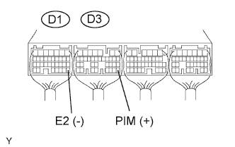
Standard voltage Tester Connection Condition Specified Condition D3-28 (PIM) - D1-28 (E2) Applied negative pressure of 40 kPa (300 mmHg, 11.8 in.Hg) 1.3 to 1.9 V D3-28 (PIM) - D1-28 (E2) Same as atmospheric pressure 2.4 to 3.1 V D3-28 (PIM) - D1-28 (E2) Applied positive pressure of 170 kPa (1,275 mmHg, 50.2 in.Hg) 3.7 to 4.3 V
OK :REPLACE ECM
REPLACE ECM
NG :
-
-
CHECK HARNESS AND CONNECTOR (MANIFOLD ABSOLUTE PRESSURE SENSOR - ECM)
-
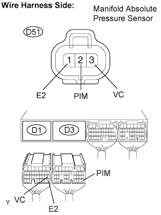
Disconnect the D51 sensor connector.
-
Disconnect the D3 and D1 ECM connectors.
-
Measure the resistance of the wire harness side connectors.
Standard resistance Tester Connection Specified Condition D51-2 (PIM) - D3-28 (PIM) Below 1 Ω D51-3 (VC) - D1-18 (VC) Below 1 Ω D51-1 (E2) - D1-28 (E2) Below 1 Ω D51-2 (PIM) or D3-28 (PIM) - Body ground 10 kΩ or higher D51-3 (VC) or D1-18 (VC) - Body ground 10 kΩ or higher D51-1 (E2) or D1-28 (E2) - Body ground 10 kΩ or higher
NG :REPAIR OR REPLACE HARNESS AND CONNECTOR
REPAIR OR REPLACE HARNESS AND CONNECTOR
OK :
-
-
INSPECT TURBOCHARGER SUB-ASSEMBLY
-
Check the turbocharger sub-assembly. Click here
OK None of the inspection results show any abnormalities.
NG :REPLACE TURBOCHARGER SUB-ASSEMBLY
REPLACE TURBOCHARGER SUB-ASSEMBLY
OK :
-
-
INSPECT EGR VALVE ASSEMBLY
-
Check the EGR valve assembly. Click here
OK None of the inspection results show any abnormalities.
NG :REPLACE EGR VALVE ASSEMBLY
REPLACE EGR VALVE ASSEMBLY
OK :REPLACE MANIFOLD ABSOLUTE PRESSURE SENSOR 
REPLACE MANIFOLD ABSOLUTE PRESSURE SENSOR
-
When not using intelligent tester:
PROCEDURE
-
CHECK ECM TERMINAL VOLTAGE (VC TERMINAL)
-
Turn the ignition switch ON.
-
Measure the voltage of the ECM connector.
Standard voltage Tester Connection Specified Condition D1-18 (VC) - D1-28 (E2) 4.5 to 5.5 V
NG :REPLACE ECM
REPLACE ECM
OK :
-
-
CHECK MANIFOLD ABSOLUTE PRESSURE SENSOR
-
Turn the ignition switch ON.
-
Apply pressure to the manifold absolute pressure sensor. Click here
-
Measure the voltage of the ECM connectors.
Standard voltage Tester Connection Condition Specified Condition D3-28 (PIM) - D1-28 (E2) Applied negative pressure of 40 kPa (300 mmHg, 11.8 in.Hg) 1.3 to 1.9 V D3-28 (PIM) - D1-28 (E2) Same as atmospheric pressure 2.4 to 3.1 V D3-28 (PIM) - D1-28 (E2) Applied positive pressure of 170 kPa (1,275 mmHg, 50.2 in.Hg) 3.7 to 4.3 V
OK :REPLACE ECM
REPLACE ECM
NG :
-
-
CHECK HARNESS AND CONNECTOR (MANIFOLD ABSOLUTE PRESSURE SENSOR - ECM)
-
Disconnect the D51 sensor connector.
-
Disconnect the D3 and D1 ECM connectors.
-
Measure the resistance of the wire harness side connectors.
Standard resistance Tester Connection Specified Condition D51-2 (PIM) - D3-28 (PIM) Below 1 Ω D51-3 (VC) - D1-18 (VC) Below 1 Ω D51-1 (E2) - D1-28 (E2) Below 1 Ω D51-2 (PIM) or D3-28 (PIM) - Body ground 10 kΩ or higher D51-3 (VC) or D1-18 (VC) - Body ground 10 kΩ or higher D51-1 (E2) or D1-28 (E2) - Body ground 10 kΩ or higher
NG :REPAIR OR REPLACE HARNESS AND CONNECTOR
REPAIR OR REPLACE HARNESS AND CONNECTOR
OK :
-
-
INSPECT TURBOCHARGER SUB-ASSEMBLY
-
Check the turbocharger sub-assembly. Click here
OK None of the inspection results show any abnormalities.
NG :REPLACE TURBOCHARGER SUB-ASSEMBLY
REPLACE TURBOCHARGER SUB-ASSEMBLY
OK :
-
-
INSPECT EGR VALVE ASSEMBLY
-
Check the EGR valve assembly. Click here
OK None of the inspection results show any abnormalities.
NG :REPLACE EGR VALVE ASSEMBLY
REPLACE EGR VALVE ASSEMBLY
OK :REPLACE MANIFOLD ABSOLUTE PRESSURE SENSOR
REPLACE MANIFOLD ABSOLUTE PRESSURE SENSOR
-