REAR STRUT ROD INSTALLATION
-
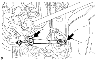
TEMPORARILY INSTALL REAR STRUT ROD ASSEMBLY (for 2WD)
-
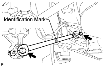
Check that the identification mark of the rear strut rod assembly is positioned on the inner side of the vehicle.
-
Temporarily install the rear strut rod assembly with the 2 bolts and the 2 nuts.
Note
Since stopper nuts are used, temporarily tighten the bolts.
-
-
TEMPORARILY INSTALL REAR STRUT ROD ASSEMBLY (for 4WD)
-
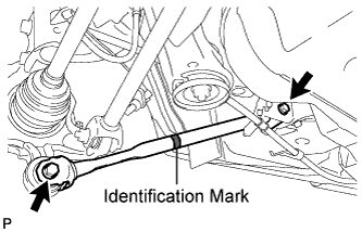
Check that the identification mark of the rear strut rod assembly is positioned on the inner side of the vehicle.
-
Temporarily install the rear strut rod assembly with the 2 bolts and the 2 nuts.
Note
Since stopper nuts are used, temporarily tighten the bolts.
-
-
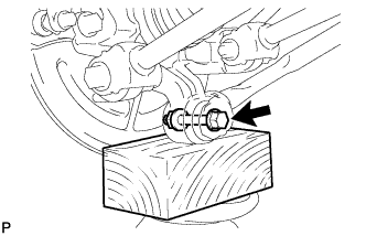
STABILIZE SUSPENSION (for 2WD)
-
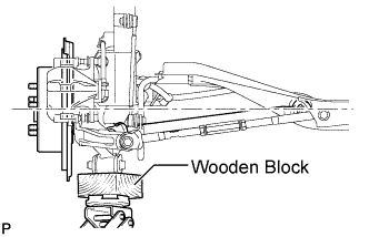
Jack up the rear axle carrier, placing a wooden block underneath to avoid damage. Apply load to the suspension so that the installed bolt of the rear No. 1 suspension arm (inner side) is horizontally aligned with the center of the rear axle hub.
CAUTION:
Do not jack up the rear axle carrier subassembly too high as the vehicle may fall.
Note
Do not bend the brake dust cover.
Tech Tips
-
If the rear drive shaft assembly cannot be positioned horizontally as shown in the illustration even when the rear axle carrier subassembly is jacked up, apply additional load to the vehicle such as by having a person sit in the rear seat.
-
Use the same procedures for the RH side and LH side.
-
-
-
STABILIZE SUSPENSION (for 4WD)
-
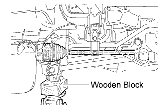
Jack up the rear axle carrier sub-assembly, placing a wooden block underneath to avoid damage. Apply load to the suspension so that the rear drive shaft assembly is positioned horizontally.
CAUTION:
Do not jack up the rear axle carrier sub-assembly too high as the vehicle may fall.
Note
Do not bend the brake dust cover.
Tech Tips
-
If the rear drive shaft assembly cannot be positioned horizontally as shown in the illustration even when the rear axle carrier sub-assembly is jacked up, apply additional load to the vehicle such as by having a person sit in the rear seat.
-
Use the same procedure for the RH side and LH side.
-
-
-
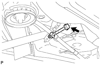
FULLY TIGHTEN REAR STRUT ROD ASSEMBLY (for 2WD)
-
Fully tighten the 2 bolts.
- Torque:
- 80 N*m { 815 kgf*cm, 59 ft.*lbf }
Note
-
Since stopper nuts are used, fully tighten the bolts.
-
The final torque must be applied under standard vehicle height conditions.
-
-
FULLY TIGHTEN REAR STRUT ROD ASSEMBLY (for 4WD)
-
Fully tighten the bolt.
- Torque:
- 80 N*m { 815 kgf*cm, 59 ft.*lbf }
Note
-
Since a stopper nut is used, fully tighten the bolt.
-
The final torque must be applied under standard vehicle height conditions.
-
Fully tighten the bolt.
- Torque:
- 80 N*m { 815 kgf*cm, 59 ft.*lbf }
Note
-
Since a stopper nut is used, fully tighten the bolt.
-
The final torque must be applied under standard vehicle height conditions.
-
-
INSTALL NO. 3 PARKING BRAKE CABLE ASSEMBLY
-
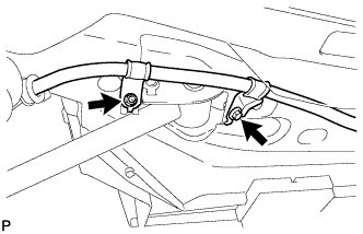
Install the No. 3 parking brake cable assembly with the bolt and the nut.
- Torque:
- Bolt
- 39 N*m { 397 kgf*cm, 29 ft.*lbf }
- Nut
- 6.0 N*m { 61 kgf*cm, 53 in.*lbf }
Note
Do not twist the No. 3 parking brake cable assembly when installing it.
-
-
INSTALL REAR WHEEL
- Torque:
- 103 N*m { 1050 kgf*cm, 76 ft.*lbf }