- Click here
REMOVE REAR WHEELS
- Click here
REMOVE TAIL EXHAUST PIPE ASSEMBLY
-
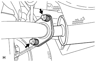
Remove the 2 bolts and 2 compression springs.
-
Disconnect the exhaust pipe support and remove the tail exhaust pipe assembly.
-
Remove the gasket from the center exhaust pipe assembly.
-
- Click here
REMOVE CENTER EXHAUST PIPE ASSEMBLY
-
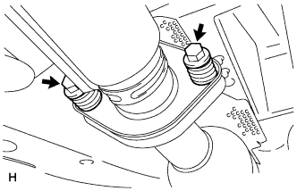
Remove the 2 bolts and 2 compression springs.
-
Disconnect the 3 exhaust pipe supports and remove the center exhaust pipe assembly.
-
Remove the gasket from the No. 3 exhaust pipe sub-assembly.
-
- Click here
REMOVE PROPELLER WITH CENTER BEARING SHAFT ASSEMBLY
-
Depress the brake pedal and hold it.
-
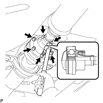
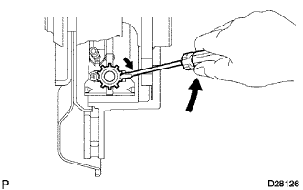
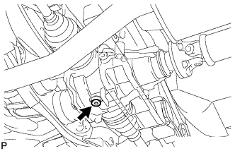
Using a hexagon wrench (6 mm), loosen the cross groove joint set bolts 1/2 turn.
Tip:Put a piece of cloth or equivalent into the inside of the universal joint cover so that the boot does not touch the inside of the universal joint cover.
-
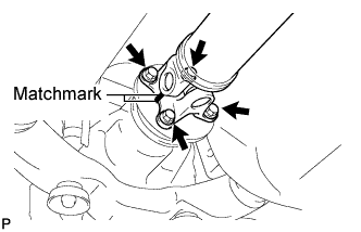
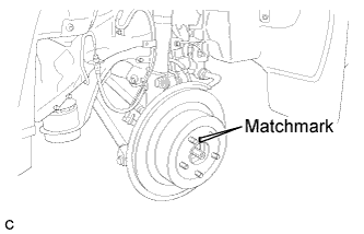
Place matchmarks on the rear propeller shaft and rear drive pinion flange sub-assembly.
-
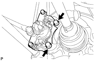
Remove the 4 nuts, 4 bolts and 4 washers.
-
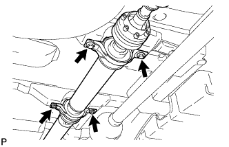
Remove the 4 bolts and 4 adjusting shims.
-
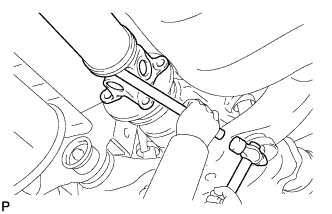
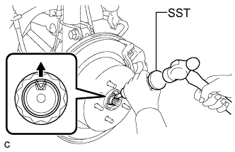
Using a brass bar and a hammer, remove the propeller shaft with center bearing shaft assembly.
-
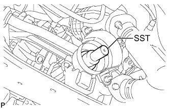
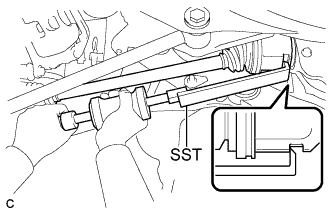
Insert SST into the transfer to prevent oil leakage.
09325-20010
-
- Click here
SEPARATE REAR SPEED SENSOR LH
-
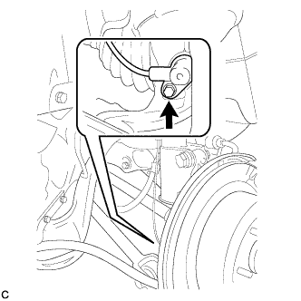
Remove the bolt and separate the rear speed sensor from the rear axle carrier sub-assembly.
Note:Keep the sensor tip and rear speed sensor installation hole free from foreign matter.
-
- Click here
SEPARATE REAR SPEED SENSOR RH
Tip:Perform the same procedure as the LH side.
- Click here
REMOVE REAR AXLE SHAFT NUT LH
-
Using SST and a hammer, release the staked part of the rear axle shaft nut.
09930-00010 Note:Loosen the staked part of the nut completely, otherwise the threads of the drive shaft may be damaged.
-
While applying the brakes, remove the rear axle shaft nut.
-
- Click here
REMOVE REAR AXLE SHAFT NUT RH
Tip:Perform the same procedure as the LH side.
- Click here
SEPARATE REAR DISC BRAKE CALIPER ASSEMBLY LH
-
Remove the 2 bolts and separate the rear disc brake caliper assembly.
Note:Use wire or an equivalent tool to keep the brake caliper from hanging down by the flexible hose.
-
- Click here
SEPARATE REAR DISC BRAKE CALIPER ASSEMBLY RH
Tip:Perform the same procedure as the LH side.
- Click here
REMOVE REAR DISC (for LH Side)
-
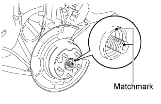
Put matchmarks on the rear disc and the axle hub.
-
Release the parking brake and remove the rear disc.
Tip:If the disc cannot be removed easily, turn and press firmly the shoe adjuster until the wheel comes free.
-
- Click here
REMOVE REAR DISC (for RH Side)
Tip:Perform the same procedure as the LH side.
- Click here
REMOVE REAR AXLE HUB AND BEARING ASSEMBLY LH
-
Put matchmarks on the drive shaft and axle hub.
Note:Do not punch the marks.
-
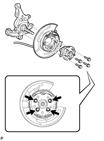
Remove the 4 bolts and the rear axle hub and bearing assembly.
Note:
-
Do not rotate the drive shaft with the rear axle hub and bearing assembly removed.
-
Use wire or an equivalent tool to keep the parking brake assembly from hanging down by the parking brake cable assembly.
-
-
- Click here
REMOVE REAR AXLE HUB AND BEARING ASSEMBLY RH
Tip:Perform the same procedure as the LH side.
- Click here
SEPARATE NO. 3 PARKING BRAKE CABLE ASSEMBLY
-
Remove the bolt and the nut, and separate the No. 3 parking brake cable assembly.
-
- Click here
SEPARATE NO. 2 PARKING BRAKE CABLE ASSEMBLY
Tip:Perform the same procedure as the No. 3 parking brake cable assembly.
- Click here
REMOVE REAR STRUT ROD ASSEMBLY LH
-
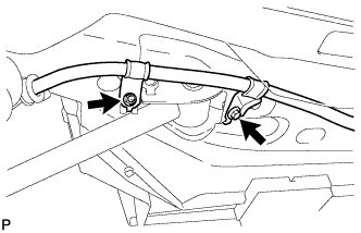
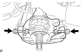
Remove the 2 bolts, the 2 nuts, and the rear strut rod assembly.
Note:Since stopper nuts are used, loosen the bolts.
-
- Click here
REMOVE REAR STRUT ROD ASSEMBLY RH
Tip:Perform the same procedure as the LH side.
- Click here
REMOVE REAR AXLE CARRIER SUB-ASSEMBLY LH
-
Loosen the 2 bolts.
Note:Since stopper nuts are used, loosen the bolts.
-
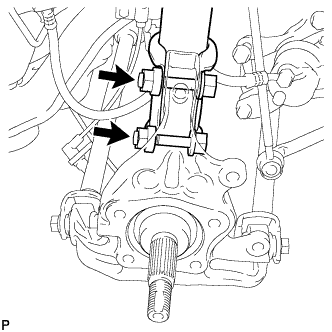
Remove the 2 bolts and 2 nuts, and separate the rear shock absorber with coil spring (lower side) from the rear axle carrier sub-assembly.
Note:
-
Be careful not to damage the outboard joint boot.
-
Be careful not to damage the speed sensor rotor.
-
-
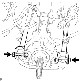
Remove the 2 bolts, the 2 nuts, and the rear axle carrier sub-assembly.
Note:
-
Be careful not to damage the outboard joint boot.
-
Be careful not to damage the speed sensor rotor.
Tip:Use wire or an equivalent tool to keep the rear drive shaft assembly from hanging down.
-
-
- Click here
REMOVE REAR AXLE CARRIER SUB-ASSEMBLY RH
Tip:Perform the same procedure as the LH side.
-
Click here
REMOVE REAR NO. 2 SUSPENSION ARM ASSEMBLY LH
-
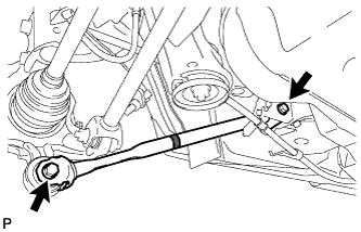
Put matchmarks on the adjust cams and the rear suspension member sub-assembly.
-
Remove the nut, the No. 2 camber adjust cam, the rear suspension toe adjust cam sub-assembly, and the rear No. 2 suspension arm assembly LH.
Note:Mark the removed parts to distinguish left from right and keep them in order for reinstallation.
Tip:When removing the nut, keep the rear suspension toe adjust cam sub-assembly from rotating.
-
- Click here
REMOVE REAR NO. 2 SUSPENSION ARM ASSEMBLY RH
Tip:Perform the same procedure as the LH side.
-
Click here
REMOVE REAR NO. 1 SUSPENSION ARM ASSEMBLY RH
-
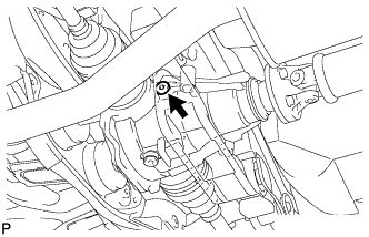
Remove the bolt, the nut, and the rear No. 1 suspension arm assembly RH from the rear suspension member sub-assembly.
Note:
-
Since a stopper nut is used, loosen the bolt.
-
Mark the removed parts to distinguish left from right and keep them in order for reinstallation.
-
-
- Click here
REMOVE REAR DIFFERENTIAL FILLER PLUG
-
Using a hexagon wrench (10 mm), remove the rear differential filler plug and rear differential filler plug gasket.
-
- Click here
REMOVE REAR DIFFERENTIAL DRAIN PLUG
-
Using a hexagon wrench (10 mm), remove the rear differential drain plug and rear differential drain plug gasket, and drain the oil.
-
- Click here
REMOVE REAR DRIVE SHAFT ASSEMBLY LH
-
Using SST, remove the rear drive shaft assembly as shown in the illustration.
09520-01010 09520-24010 09520-32040 Note:Remove the rear drive shaft assembly while keeping it level.
-
- Click here
REMOVE REAR DRIVE SHAFT SNAP RING LH
-
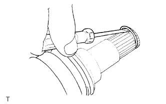
Using a screwdriver, remove the rear drive shaft snap ring.
-
- Click here
REMOVE REAR DRIVE SHAFT ASSEMBLY RH
Tip:Perform the same procedure as the LH side.
- Click here
REMOVE REAR DRIVE SHAFT SNAP RING RH
Tip:Perform the same procedure as the LH side.
- Click here
REMOVE REAR SUSPENSION MEMBER
-
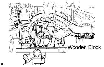
Support the rear suspension member with a jack using a wooden block.
Tip:Use a properly sized wooden block to keep the jack and suspension member level.
-
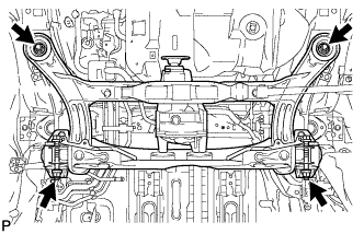
Remove the 4 nuts, 2 bolts and 2 rear lower suspension member stopper retainers.
-
Lower the rear suspension member.
-
Remove the 2 rear upper suspension member stoppers.
-
-
Click here
REMOVE REAR NO. 1 SUSPENSION ARM ASSEMBLY LH
-
Remove the bolt, the nut, and the rear No. 1 suspension arm assembly LH from the rear suspension member sub-assembly.
Note:Since a stopper nut is used, loosen the bolt.
-
- Click here
REMOVE REAR DIFFERENTIAL CARRIER ASSEMBLY
-
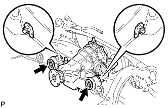
Support the rear differential carrier assembly with a jack.
-
Remove the 2 bolts and 2 lock nuts, and separate the No. 1 rear differential support from the rear suspension member sub-assembly.
-
Remove the 3 bolts and rear differential carrier assembly from the rear suspension member sub-assembly.
Note:Be careful not to drop the rear differential carrier assembly.
-
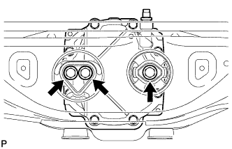
- Click here
REMOVE REAR NO. 1 DIFFERENTIAL MOUNT CUSHION
-
Using SST, remove the rear No. 1 differential mount cushion.
09570-24011 09316-12010 Note:
-
Do not bring SST into contact with the sub-frame.
-
Do not slant the SST bolt.
-
Do not set SST in the wrong direction.
-
Tighten the SST bolt equally into the 2 No. 1 rear differential mount cushion hole.
Tip:Perform this operation only if the No. 1 rear differential mount cushion is damaged.
-
-
- Click here
REMOVE REAR NO. 2 DIFFERENTIAL MOUNT CUSHION
-
Using SST, remove the rear No. 2 differential mount cushion.
09570-24011 09316-12010 Note:
-
Do not bring SST into contact with the sub-frame.
-
Do not slant the SST bolts.
-
Do not set SST in the wrong direction.
Tip:Perform this operation only if the No. 2 rear differential mount cushion is damaged.
-
-
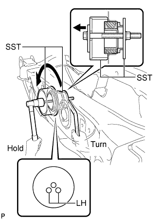
- Click here
REMOVE REAR SUSPENSION MEMBER BODY MOUNTING FRONT CUSHION (for LH Side)
-
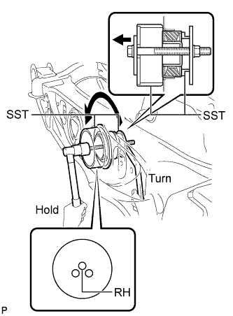
Using SST, remove the rear suspension member body mounting front cushion.
09830-10010 09830-01010 09830-01040 09830-01050 09950-40011 09951-04020 09952-04010 09955-04011 09954-04010 09958-04011 Note:
-
Set the tips of the claws in the cutouts of the body mounting cushion.
-
Securely install the spacer No. 1 to the inner cylinder of the body mounting cushion as shown in the illustration.
-
Apply a small amount of grease to the threads of SST (center bolt) before use.
-
Tighten SST slowly and evenly.
-
Be careful as the body mounting cushion may fly out.
-
The body mounting cushion cannot be reused.
-
-
- Click here
REMOVE REAR SUSPENSION MEMBER BODY MOUNTING FRONT CUSHION (for RH Side)
Tip:Perform the same procedure as the LH side.
- Click here
REMOVE REAR SUSPENSION MEMBER BODY MOUNTING REAR CUSHION (for LH Side)
-
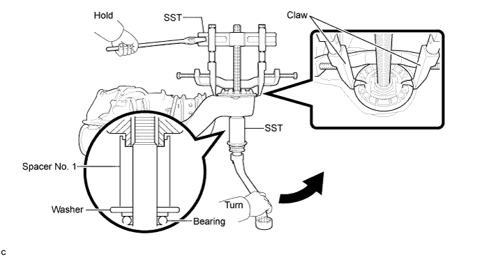
Using SST, temporarily remove the rear suspension member body mounting rear cushion.
09710-30050 09950-40011 09951-04020 09955-04031 09954-04010 09952-04010 09958-04011 09953-04010 Note:
-
Set the tips of the claws in the cutouts of the body mounting cushion.
-
Securely install the spacer No. 1 to the inner cylinder of the body mounting cushion as shown in the illustration.
-
Apply a small amount of grease to the threads of SST (center bolt) before use.
-
Tighten SST slowly and evenly.
-
Be careful as the body mounting cushion may fly out.
-
The body mounting cushion cannot be reused.
-
-
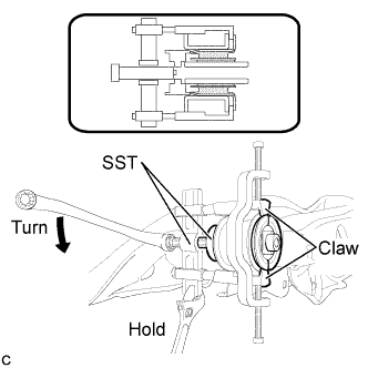
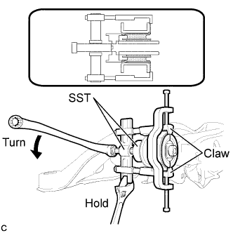
When the mounting cushion protrudes approximately 6 mm, reassemble SST as shown in the illustration and remove the mounting cushion.
09710-30050 09950-40011 09951-04020 09955-04031 09954-04010 09952-04010 09958-04011 09953-04010 09953-04020 Note:
-
Set the tips of the claws in the cutouts of the body mounting cushion.
-
Securely install the spacer No. 1 to the inner cylinder of the body mounting cushion as shown in the illustration.
-
Apply a small amount of grease to the threads of SST (center bolt) before use.
-
Tighten SST slowly and evenly.
-
Be careful as the body mounting cushion may fly out.
-
The body mounting cushion cannot be reused.
Tip:Use the shorter center bolt first, and then change it to the longer center bolt.
-
-
- Click here
REMOVE REAR SUSPENSION MEMBER BODY MOUNTING REAR CUSHION (for RH Side)
Tip:Perform the same procedure as the LH side.
- Click here
REMOVE HOLE PLUG
-
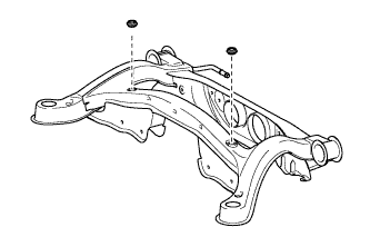
Remove the 2 hole plugs.
-
- Click here
REMOVE REAR NO. 2 BODY MOUNTING BRACKET SUB-ASSEMBLY LH
-
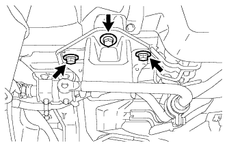
Remove the 3 bolts and rear No. 2 body mounting bracket sub-assembly LH.
-
- Click here
REMOVE REAR NO. 2 BODY MOUNTING BRACKET SUB-ASSEMBLY RH
-
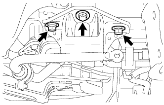
Remove the 3 bolts and rear No. 2 body mounting bracket sub-assembly RH.
-
- Click here
REMOVE STUD BOLT (for LH Side)
-
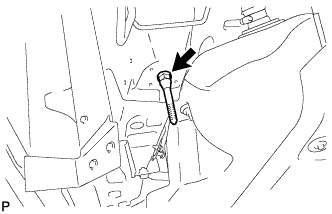
Remove the stud bolt.
-
- Click here
REMOVE STUD BOLT (for RH Side)
Tip:Perform the same procedure as the LH side.