REAR SUSPENSION MEMBER (for 2WD) INSTALLATION
-
INSTALL STUD BOLT (for LH Side)
-
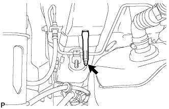
Install the stud bolt.
- Torque:
- 17 N*m { 173 kgf*cm, 12 ft.*lbf }
-
-
INSTALL STUD BOLT (for RH Side)
Tech Tips
Perform the same procedure as the LH side.
-
INSTALL HOLE PLUG
-
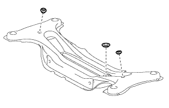
Install the hole plugs to the rear suspension member sub-assembly.
Tech Tips
There are two sizes of hole plugs.
-
-
INSTALL REAR SUSPENSION MEMBER BODY MOUNTING FRONT CUSHION LH
-
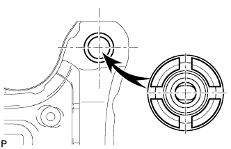
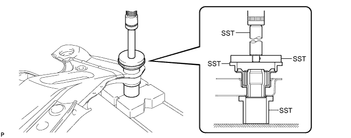
Temporarily install a new rear suspension member body mounting front cushion LH to the position shown in the illustration.
-
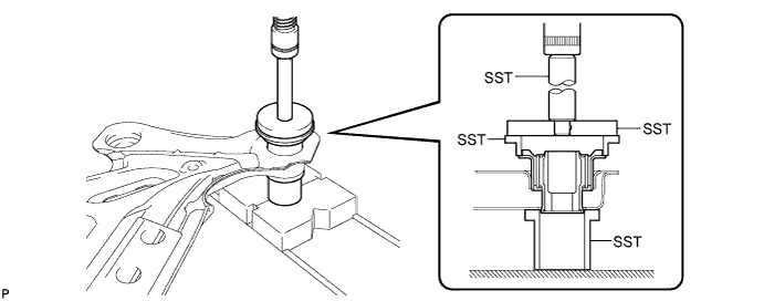
Using SST and a press, install the rear suspension member body mounting front cushion LH to the rear suspension member sub-assembly.
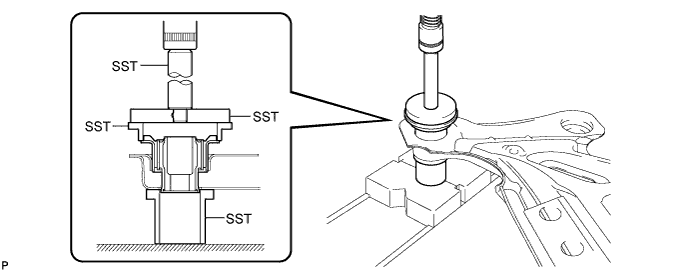
- SST
- 09950-70010 ( 09951-07100 )
- 09950-60020 ( 09951-00890 )
- 09502-12010
- 09515-30010
Tech Tips
Slowly press in the mounting cushion.
-
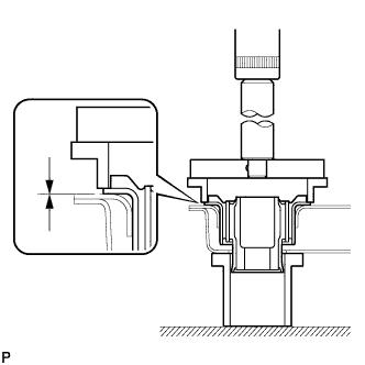
While observing from the side, press in the rear suspension member body mounting front cushion LH until there is no clearance between the rear suspension member body mounting front cushion LH and the rear suspension member sub-assembly as shown in the illustration.
Note
Do not press the rear suspension member excessively, or it will easily deform.
-
-
INSTALL REAR SUSPENSION MEMBER BODY MOUNTING FRONT CUSHION RH
-
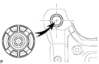
Temporarily install a new rear suspension member body mounting front cushion RH to the position shown in the illustration.
-
Using SST and a press, install the rear suspension member body mounting front cushion RH to the rear suspension member sub-assembly.
- SST
- 09950-70010 ( 09951-07100 )
- 09950-60020 ( 09951-00890 )
- 09502-12010
- 09515-30010
Tech Tips
Slowly press in the mounting cushion.
-
While observing from the side, press in the rear suspension member body mounting front cushion RH until there is no clearance between the rear suspension member body mounting front cushion RH and the rear suspension member sub-assembly as shown in the illustration.
Note
Do not press the rear suspension member excessively, or it will easily deform.
-
-
INSTALL REAR SUSPENSION MEMBER BODY MOUNTING REAR CUSHION (for LH Side)
-
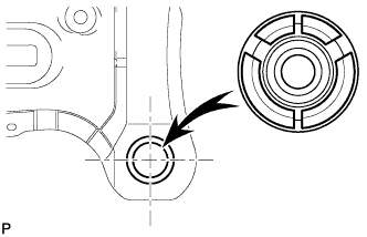
Temporarily install a new rear suspension member body mounting rear cushion (LH side) to the position shown in the illustration.
-
Using SST and a press, install the rear suspension member body mounting rear cushion (LH side) to the rear suspension member sub-assembly.
- SST
- 09950-70010 ( 09951-07100 )
- 09950-60020 ( 09951-00890 )
- 09502-12010
- 09515-30010
Tech Tips
Slowly press in the mounting cushion.
-
While observing from the side, press in the rear suspension member body mounting rear cushion (LH side) until there is no clearance between the rear suspension member body mounting rear cushion (LH side) and the rear suspension member sub-assembly as shown in the illustration.
Note
Do not press the rear suspension member excessively, or it will easily deform.
-
-
INSTALL REAR SUSPENSION MEMBER BODY MOUNTING REAR CUSHION (for RH Side)
Tech Tips
Perform the same procedure as the LH side.
-
INSTALL REAR SUSPENSION MEMBER
-
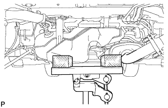
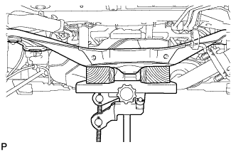
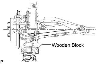
Set the jack and wooden blocks below the vehicle as shown in the illustration.
-
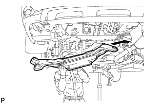
Set the rear suspension member onto the jack as shown in the illustration.
Note
When removing the rear suspension member, be careful not to damage the vehicle body or other components installed on the vehicle.
-
Raise the rear suspension member with a jack.
-
Install the rear suspension member and the rear lower suspension member stoppers LH and RH with the 4 nuts.
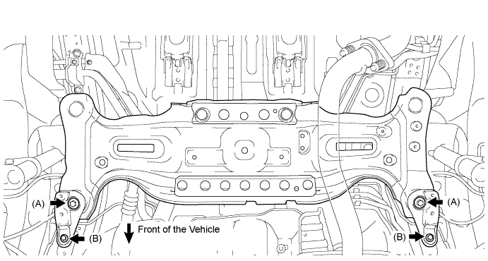
- Torque:
- Nut A
- 55 N*m { 561 kgf*cm, 40 ft.*lbf }
- Nut B
- 38 N*m { 387 kgf*cm, 28 ft.*lbf }
-
Install the rear suspension member and the rear lower suspension member stoppers with the 2 bolts.
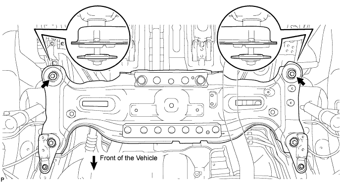
- Torque:
- 55 N*m { 561 kgf*cm, 40 ft.*lbf }
Note
Be sure to install the rear suspension member with the rear lower suspension member stopper in the correct direction as shown in the illustration.
-
-
INSTALL EXHAUST PIPE CLAMP BRACKET SUB-ASSEMBLY
-
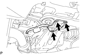
Install the exhaust pipe clamp bracket sub-assembly with the 3 bolts.
-
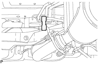
Install the exhaust pipe clamp to the exhaust pipe clamp bracket sub-assembly.
-
-
TEMPORARILY INSTALL REAR NO. 1 SUSPENSION ARM ASSEMBLY LH
-
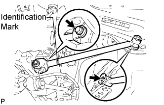
Temporarily install the rear No. 1 suspension arm assembly to the rear suspension member with the bolt.
Note
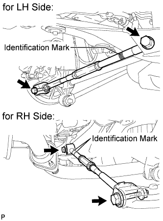
Ensure that the identification mark faces the rear side of the vehicle.
-
Temporarily install the rear No. 1 suspension arm assembly to the rear axle carrier sub-assembly with the bolt and the nut.
Note
Since a stopper nut is used, temporarily tighten the bolt.
-
-
TEMPORARILY INSTALL REAR NO. 1 SUSPENSION ARM ASSEMBLY RH
Tech Tips
Perform the same procedure as the LH side.
-
TEMPORARILY INSTALL REAR NO. 2 SUSPENSION ARM ASSEMBLY LH
-
Temporarily install the rear No. 2 suspension arm assembly to the rear suspension member with the bolt.
Note
Ensure that the identification mark faces the rear side of the vehicle.
-
Temporarily install the rear No. 2 suspension arm assembly to the rear axle carrier sub-assembly with the bolt and the nut.
Note
Since a stopper nut is used, temporarily tighten the bolt.
-
-
TEMPORARILY INSTALL REAR NO. 2 SUSPENSION ARM ASSEMBLY RH
Tech Tips
Perform the same procedure as the LH side.
-
STABILIZE SUSPENSION
-
Jack up the rear axle carrier, placing a wooden block underneath to avoid damage. Apply load to the suspension so that the installed bolt of the rear No. 1 suspension arm (inner side) is horizontally aligned with the center of the rear axle hub.
CAUTION:
Do not jack up the rear axle carrier subassembly too high as the vehicle may fall.
Note
Do not bend the brake dust cover.
Tech Tips
-
If the rear drive shaft assembly cannot be positioned horizontally as shown in the illustration even when the rear axle carrier subassembly is jacked up, apply additional load to the vehicle such as by having a person sit in the rear seat.
-
Use the same procedures for the RH side and LH side.
-
-
-
FULLY TIGHTEN REAR NO. 1 SUSPENSION ARM ASSEMBLY LH
-
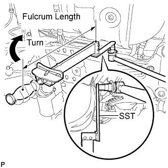
Using SST and a socket wrench (19 mm), fully tighten the bolt.
- Torque:
- without SST
- 120 N*m { 1223 kgf*cm, 88 ft.*lbf }
- with SST
- 89 N*m { 904 kgf*cm, 65 ft.*lbf }
- SST
- 09961-00950
Note
-
Use a torque wrench with a fulcrum length of 425 mm (16.73 in.).
-
This torque value is effective when SST is parallel to the torque wrench.
-
The final torque must be applied under standard vehicle height conditions.
-
Fully tighten the bolt
- Torque:
- 112 N*m { 1141 kgf*cm, 82 ft.*lbf }
Note
-
Since a stopper nut is used, fully tighten the bolt.
-
The final torque must be applied under standard vehicle height conditions.
-
-
FULLY TIGHTEN REAR NO. 1 SUSPENSION ARM ASSEMBLY RH
Tech Tips
Perform the same procedure as the LH side.
-
FULLY TIGHTEN REAR NO. 2 SUSPENSION ARM ASSEMBLY LH
-
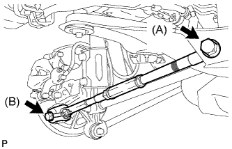
Fully tighten the bolts.
- Torque:
- Bolt (A)
- 120 N*m { 1223 kgf*cm, 88 ft.*lbf }
- Bolt (B)
- 112 N*m { 1141 kgf*cm, 82 ft.*lbf }
Note
-
Since a stopper nut is used, fully tighten the bolt.
-
The final torque must be applied under standard vehicle height conditions.
-
-
FULLY TIGHTEN REAR NO. 2 SUSPENSION ARM ASSEMBLY RH
Tech Tips
Perform the same procedure as the LH side.
-
INSTALL REAR STABILIZER BAR
-
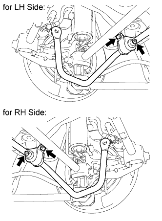
Install the rear stabilizer bar with the 4 bolts.
- Torque:
- 19 N*m { 194 kgf*cm, 14 ft.*lbf }
-
-
INSTALL REAR STABILIZER LINK ASSEMBLY LH
-
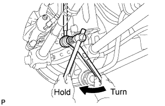
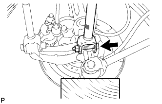
Install the rear stabilizer link assembly LH to the rear stabilizer bar with the nut.
- Torque:
- 39 N*m { 400 kgf*cm, 29 ft.*lbf }
Tech Tips
If the ball joint turns together with the nut, use a hexagon wrench (5 mm) to hold the stud bolt.
-
-
INSTALL REAR STABILIZER LINK ASSEMBLY RH
Tech Tips
Perform the same procedure as the LH side.
-
INSTALL REAR WHEELS
- Torque:
- 103 N*m { 1,050 kgf*cm, 76 ft.*lbf }
-
INSTALL SPARE WHEEL CARRIER LOCK COVER
-
INSTALL SPARE TIRE
-
INSTALL LOWER SPARE WHEEL CARRIER HINGE COVER
-
INSTALL DECK TRIM SERVICE HOLE COVER
-
INSTALL REAR MAT
-
Install the rear mat.
-
-
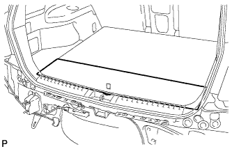
INSTALL TONNEAU COVER ASSEMBLY (w/ Tonneau Cover)
-
Install the tonneau cover assembly.
-
-
INSTALL NO. 2 DECK BOARD SUB-ASSEMBLY (w/ Tonneau Cover)
-
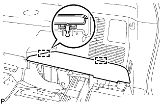
Engage the 2 guides and install the No. 2 deck board sub-assembly.
-
-
INSTALL NO. 3 DECK BOARD SUB-ASSEMBLY (w/ Tonneau Cover)
-
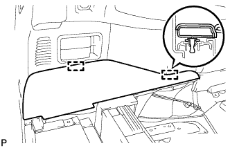
Engage the 2 guides and install the No. 3 deck board sub-assembly.
-
-
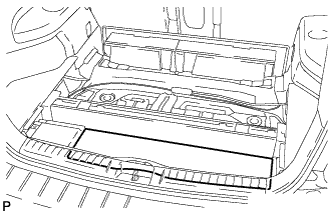
INSTALL DECK BOARD ASSEMBLY
-
Install the deck board assembly.
-
-
INSPECT AND ADJUST REAR WHEEL ALIGNMENT
Tech Tips