- Click here
REMOVE DECK BOARD ASSEMBLY
-
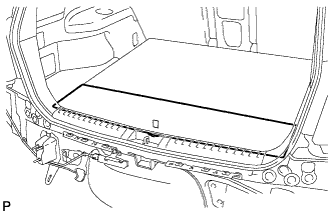
Remove the deck board assembly.
-
- Click here
REMOVE NO. 3 DECK BOARD SUB-ASSEMBLY (w/ Tonneau Cover)
-
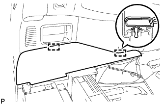
Disengage the 2 guides and remove the No. 3 deck board sub-assembly.
-
- Click here
REMOVE NO. 2 DECK BOARD SUB-ASSEMBLY (w/ Tonneau Cover)
-
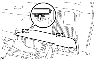
Disengage the 2 guides and remove the No. 2 deck board sub-assembly.
-
- Click here
REMOVE TONNEAU COVER ASSEMBLY (w/ Tonneau Cover)
-
Remove the tonneau cover assembly.
-
- Click here
REMOVE REAR MAT
-
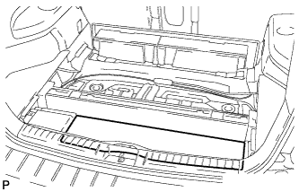
Remove the rear mat.
-
- Click here
REMOVE DECK TRIM SERVICE HOLE COVER
- Click here
REMOVE LOWER SPARE WHEEL CARRIER HINGE COVER
- Click here
REMOVE SPARE TIRE
- Click here
REMOVE SPARE WHEEL CARRIER LOCK COVER
- Click here
REMOVE REAR WHEELS
- Click here
SEPARATE REAR STABILIZER LINK ASSEMBLY LH
-
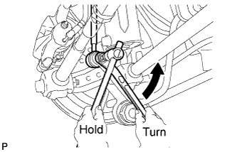
Remove the nut and separate the rear stabilizer link assembly LH from the rear stabilizer bar.
Tip:If the ball joint turns together with the nut, use a hexagon wrench (5 mm) to hold the stud bolt.
-
- Click here
SEPARATE REAR STABILIZER LINK ASSEMBLY RH
Tip:Perform the same procedure as the LH side.
- Click here
REMOVE REAR STABILIZER BAR
-
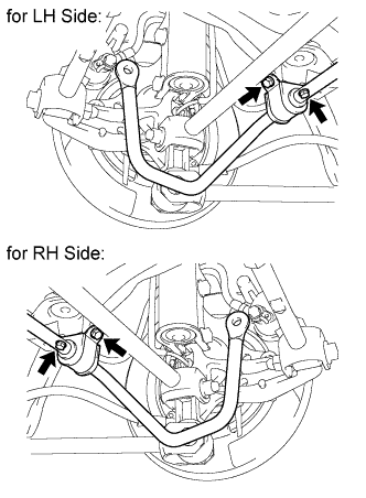
Remove the 4 bolts and rear stabilizer bar.
-
-
Click here
REMOVE REAR NO. 2 SUSPENSION ARM ASSEMBLY LH
-
Remove the bolt and the nut, and separate the rear No. 2 suspension arm assembly from the rear axle carrier sub-assembly.
Note:Since a stopper nut is used, loosen the bolt.
-
Remove the bolt and the rear No. 2 suspension arm assembly.
-
- Click here
REMOVE REAR NO. 2 SUSPENSION ARM ASSEMBLY RH
Tip:Perform the same procedure as the LH side.
-
Click here
REMOVE REAR NO. 1 SUSPENSION ARM ASSEMBLY LH
-
Remove the bolt and the nut, and separate the rear No. 1 suspension arm assembly from the rear axle carrier sub-assembly.
Note:Since a stopper nut is used, loosen the bolt.
-
Remove the bolt and the rear No. 1 suspension arm assembly.
-
- Click here
REMOVE REAR NO. 1 SUSPENSION ARM ASSEMBLY RH
Tip:Perform the same procedure as the LH side.
- Click here
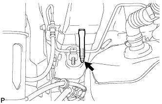
REMOVE EXHAUST PIPE CLAMP BRACKET SUB-ASSEMBLY
-
Separate the exhaust pipe clamp from the exhaust pipe clamp bracket sub-assembly.
-
Remove the 3 bolts and the exhaust pipe clamp bracket sub-assembly.
-
- Click here
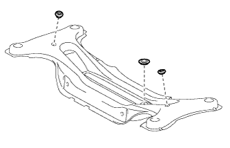
REMOVE REAR SUSPENSION MEMBER
-
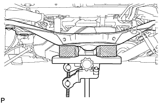
Using a jack and 2 wooden blocks, and support the rear suspension member.
-
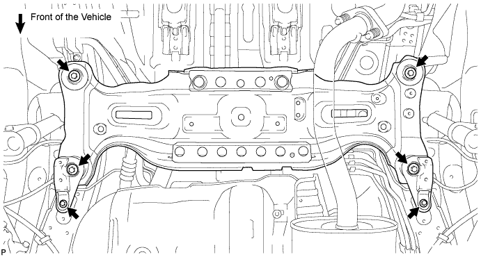
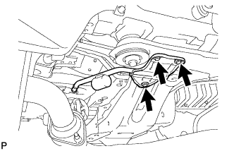
Remove the 4 nuts, the 2 bolts, and the 4 rear lower suspension member stoppers.
-
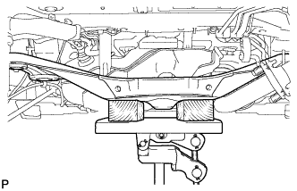
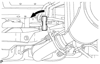
Lower the suspension member to the point shown in the illustration.
-
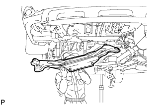
Remove the rear suspension member as shown in the illustration.
Note:When removing the rear suspension member, be careful not to damage the vehicle body or other components installed on the vehicle.
-
- Click here
REMOVE REAR SUSPENSION MEMBER BODY MOUNTING FRONT CUSHION LH
-
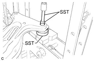
Using SST and a press, remove the rear suspension member body mounting front cushion LH from the rear suspension member sub-assembly.
09527-17011 09950-70010 09951-07100 09950-60010 09951-00340 Tip:
-
Install SST as shown in the illustration.
-
To prevent the rear suspension member sub-assembly from falling after removing the rear suspension member body mounting front cushion LH, support the rear suspension member sub-assembly using your hands and body while pressing.
-
-
- Click here
REMOVE REAR SUSPENSION MEMBER BODY MOUNTING FRONT CUSHION RH
Tip:Perform the same procedure as the LH side.
- Click here
REMOVE REAR SUSPENSION MEMBER BODY MOUNTING REAR CUSHION (for LH Side)
-
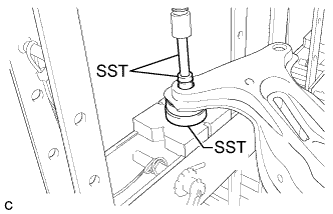
Using SST and a press, remove the rear suspension member body mounting rear cushion from the rear suspension member sub-assembly.
09527-17011 09950-70010 09951-07100 09950-60010 09951-00340 Tip:
-
Install SST as shown in the illustration.
-
To prevent the rear suspension member sub-assembly from falling after removing the rear suspension member body mounting rear cushion, support the rear suspension member sub-assembly using your hands and body while pressing.
-
-
- Click here
REMOVE REAR SUSPENSION MEMBER BODY MOUNTING REAR CUSHION (for RH Side)
Tip:Perform the same procedure as the LH side.
- Click here
REMOVE HOLE PLUG
-
Remove the 3 hole plugs from the rear suspension member sub-assembly.
Tip:There are two sizes of hole plugs.
-
- Click here
REMOVE STUD BOLT (for LH Side)
-
Remove the stud bolt.
-
- Click here
REMOVE STUD BOLT (for RH Side)
Tip:Perform the same procedure as the LH side.