REAR SUSPENSION MEMBER (for 2WD) REMOVAL
-
REMOVE DECK BOARD ASSEMBLY
-
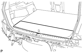
Remove the deck board assembly.
-
-
REMOVE NO. 3 DECK BOARD SUB-ASSEMBLY (w/ Tonneau Cover)
-
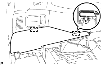
Disengage the 2 guides and remove the No. 3 deck board sub-assembly.
-
-
REMOVE NO. 2 DECK BOARD SUB-ASSEMBLY (w/ Tonneau Cover)
-
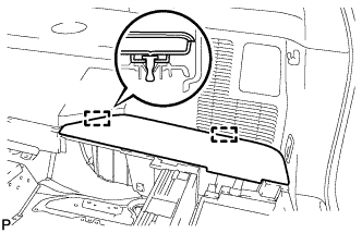
Disengage the 2 guides and remove the No. 2 deck board sub-assembly.
-
-
REMOVE TONNEAU COVER ASSEMBLY (w/ Tonneau Cover)
-
Remove the tonneau cover assembly.
-
-
REMOVE REAR MAT
-
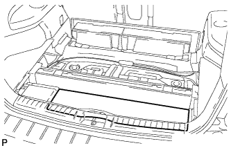
Remove the rear mat.
-
-
REMOVE DECK TRIM SERVICE HOLE COVER
-
REMOVE LOWER SPARE WHEEL CARRIER HINGE COVER
-
REMOVE SPARE TIRE
-
REMOVE SPARE WHEEL CARRIER LOCK COVER
-
REMOVE REAR WHEELS
-
SEPARATE REAR STABILIZER LINK ASSEMBLY LH
-
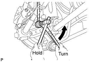
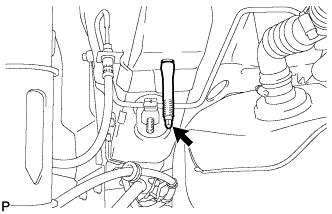
Remove the nut and separate the rear stabilizer link assembly LH from the rear stabilizer bar.
Tech Tips
If the ball joint turns together with the nut, use a hexagon wrench (5 mm) to hold the stud bolt.
-
-
SEPARATE REAR STABILIZER LINK ASSEMBLY RH
Tech Tips
Perform the same procedure as the LH side.
-
REMOVE REAR STABILIZER BAR
-
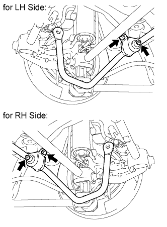
Remove the 4 bolts and rear stabilizer bar.
-
-
REMOVE REAR NO. 2 SUSPENSION ARM ASSEMBLY LH
-
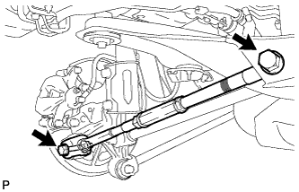
Remove the bolt and the nut, and separate the rear No. 2 suspension arm assembly from the rear axle carrier sub-assembly.
Note
Since a stopper nut is used, loosen the bolt.
-
Remove the bolt and the rear No. 2 suspension arm assembly.
-
-
REMOVE REAR NO. 2 SUSPENSION ARM ASSEMBLY RH
Tech Tips
Perform the same procedure as the LH side.
-
REMOVE REAR NO. 1 SUSPENSION ARM ASSEMBLY LH
-
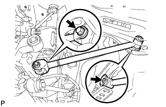
Remove the bolt and the nut, and separate the rear No. 1 suspension arm assembly from the rear axle carrier sub-assembly.
Note
Since a stopper nut is used, loosen the bolt.
-
Remove the bolt and the rear No. 1 suspension arm assembly.
-
-
REMOVE REAR NO. 1 SUSPENSION ARM ASSEMBLY RH
Tech Tips
Perform the same procedure as the LH side.
-
REMOVE EXHAUST PIPE CLAMP BRACKET SUB-ASSEMBLY
-
Separate the exhaust pipe clamp from the exhaust pipe clamp bracket sub-assembly.
-
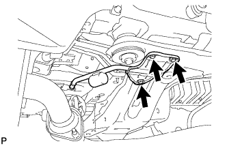
Remove the 3 bolts and the exhaust pipe clamp bracket sub-assembly.
-
-
REMOVE REAR SUSPENSION MEMBER
-
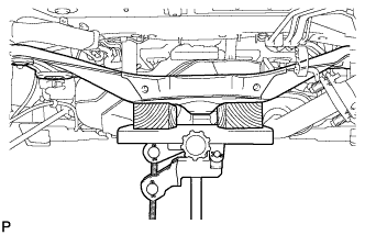
Using a jack and 2 wooden blocks, and support the rear suspension member.
-
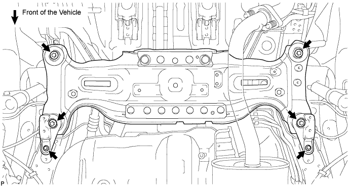
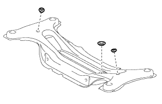
Remove the 4 nuts, the 2 bolts, and the 4 rear lower suspension member stoppers.
-
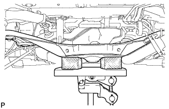
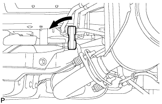
Lower the suspension member to the point shown in the illustration.
-
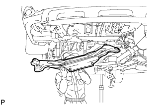
Remove the rear suspension member as shown in the illustration.
Note
When removing the rear suspension member, be careful not to damage the vehicle body or other components installed on the vehicle.
-
-
REMOVE REAR SUSPENSION MEMBER BODY MOUNTING FRONT CUSHION LH
-
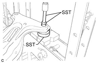
Using SST and a press, remove the rear suspension member body mounting front cushion LH from the rear suspension member sub-assembly.
- SST
- 09527-17011
- 09950-70010 ( 09951-07100 )
- 09950-60010 ( 09951-00340 )
Tech Tips
-
Install SST as shown in the illustration.
-
To prevent the rear suspension member sub-assembly from falling after removing the rear suspension member body mounting front cushion LH, support the rear suspension member sub-assembly using your hands and body while pressing.
-
-
REMOVE REAR SUSPENSION MEMBER BODY MOUNTING FRONT CUSHION RH
Tech Tips
Perform the same procedure as the LH side.
-
REMOVE REAR SUSPENSION MEMBER BODY MOUNTING REAR CUSHION (for LH Side)
-
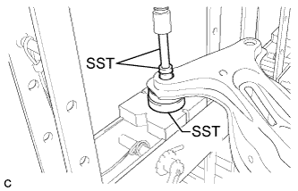
Using SST and a press, remove the rear suspension member body mounting rear cushion from the rear suspension member sub-assembly.
- SST
- 09527-17011
- 09950-70010 ( 09951-07100 )
- 09950-60010 ( 09951-00340 )
Tech Tips
-
Install SST as shown in the illustration.
-
To prevent the rear suspension member sub-assembly from falling after removing the rear suspension member body mounting rear cushion, support the rear suspension member sub-assembly using your hands and body while pressing.
-
-
REMOVE REAR SUSPENSION MEMBER BODY MOUNTING REAR CUSHION (for RH Side)
Tech Tips
Perform the same procedure as the LH side.
-
REMOVE HOLE PLUG
-
Remove the 3 hole plugs from the rear suspension member sub-assembly.
Tech Tips
There are two sizes of hole plugs.
-
-
REMOVE STUD BOLT (for LH Side)
-
Remove the stud bolt.
-
-
REMOVE STUD BOLT (for RH Side)
Tech Tips
Perform the same procedure as the LH side.