FRONT SUSPENSION MEMBER INSTALLATION
-
INSTALL FRONT SUSPENSION MEMBER BODY MOUNTING REAR CUSHION LH
-
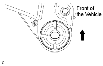
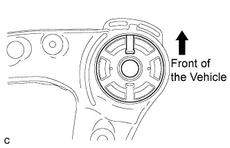
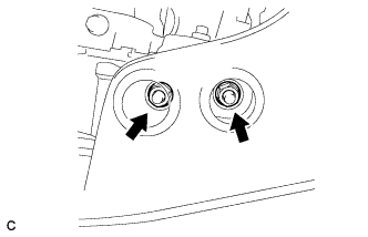
Temporarily install a new front suspension member body mounting rear cushion LH while confirming the installation direction.
Note
Position the front suspension member body mounting rear cushion in the correct direction.
-
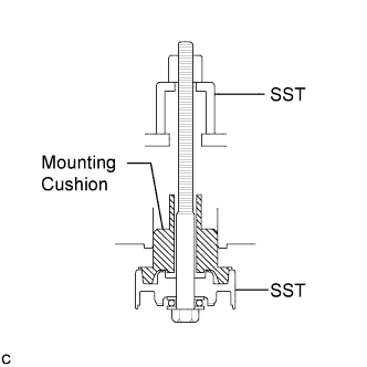
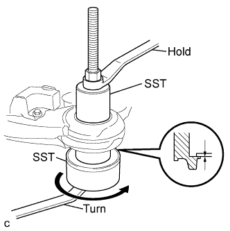
Install SST as shown in the illustration.
- SST
- 09830-10010 ( 09830-01010, 09830-01020, 09830-01030, 09830-01060 )
-
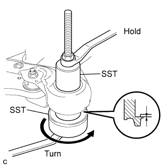
Using SST, install the front suspension member body mounting rear cushion LH as shown in the illustration.
Note
Check that there is no clearance between the front suspension member and the front suspension member body mounting rear cushion LH.
-
-
INSTALL FRONT SUSPENSION MEMBER BODY MOUNTING REAR CUSHION RH
-
Temporarily install a new front suspension member body mounting rear cushion RH while confirming the installation direction.
Note
Position the front suspension member body mounting rear cushion in the correct direction.
-
Using SST, install the front suspension member body mounting rear cushion RH.
- SST
- 09830-10010 ( 09830-01010, 09830-01020, 09830-01030, 09830-01060 )
Tech Tips
Perform the same procedure as the LH side.
-
-
INSTALL FRONT SUSPENSION MEMBER BODY MOUNTING FRONT CUSHION
-
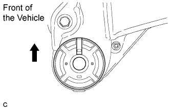
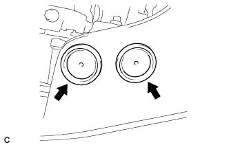
Temporarily install a new front suspension member body mounting front cushion while confirming the installation direction.
Note
Position the front suspension member body mounting front cushion in the correct direction.
-
Using SST, install the front suspension member body mounting front cushion as shown in the illustration.
- SST
- 09830-10010 ( 09830-01010, 09830-01020, 09830-01030, 09830-01060 )
Note
Check that there is no clearance between the front suspension member and the front suspension member body mounting rear cushion.
-
-
INSTALL FRONT SUSPENSION MEMBER BODY MOUNTING REAR STOPPER
-
INSTALL FRONT SUSPENSION MEMBER BODY MOUNTING FRONT STOPPER
-
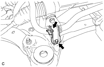
INSTALL FRONT SUSPENSION MEMBER DYNAMIC DAMPER
-
Install the front suspension member dynamic damper with the 2 bolts.
- Torque:
- 29 N*m { 296 kgf*cm, 21 ft.*lbf }
-
-
INSTALL FRONT LOWER SUSPENSION ARM LH
-
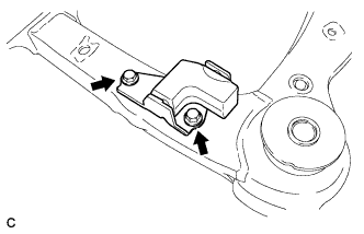
Install the front lower arm bushing stopper to the front lower suspension arm.
-
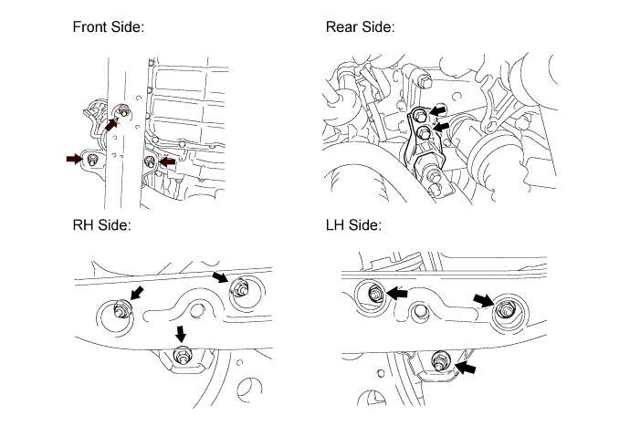
Install the front lower suspension arm to the front frame assembly with the 3 bolts and nut, but do not tighten them yet.
-
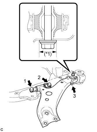
Measure the outer diameter of the washer on the bolt (3) indicated by *1 in the illustration. If the outer diameter is 32 mm (1.260 in.), replace the bolt with a type B bolt shown in the table below. If the washer outer diameter is 34 mm (1.338 in.), it is not necessary to replace the bolt.
Bolt Part Number Washer Outer Diameter Type A 90119-14116 32 mm (1.260 in.) Type B 90119-14140 32 mm (1.260 in.) Type C 90119-14126 34 mm (1.338 in.) Note
-
When removing/reinstalling the front lower suspension arm or related parts, make sure to inspect the bolt (3) in the illustration and , if necessary, replace it with a type B bolt shown in the above table.
-
There is no difference of the washer outer diameter between type A and B so that they cannot be visually distinguished.
Tech Tips
If a type B bolt was installed in an earlier procedure, it is not necessary to replace it.
-
-
Tighten the 3 bolts in numerical order shown in the illustration.
- Torque:
- Bolt 1, 2
- 200 N*m { 2039 kgf*cm, 147 ft.*lbf }
- Bolt 3
- 135 N*m { 1377 kgf*cm, 100 ft.*lbf }
Tech Tips
Start installing the bolts from the front side of the vehicle.
-
-
INSTALL FRONT LOWER SUSPENSION ARM RH
Tech Tips
Perform the same procedure as the LH side.
-
INSTALL TRANSVERSE ENGINE MOUNTING INSULATOR
-
Install the transverse engine mounting insulator with the 2 nuts.
- Torque:
- 52 N*m { 525 kgf*cm, 38 ft.*lbf }
-
Install the 2 hole plugs.
-
-
INSTALL FRONT FRAME ASSEMBLY
-
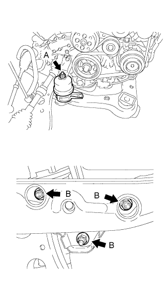
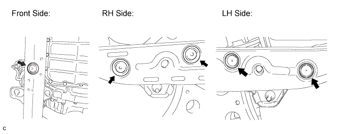
Temporarily install the engine assembly with transaxle with the 9 nuts and 2 bolts.
-
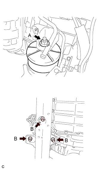
Tighten the 4 nuts.
- Torque:
- A
- 87 N*m { 887 kgf*cm, 64 ft.*lbf }
- B
- 52 N*m { 525 kgf*cm, 38 ft.*lbf }
-
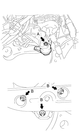
Tighten the 4 nuts.
- Torque:
- A
- 95 N*m { 969 kgf*cm, 70 ft.*lbf }
- B
- 87 N*m { 887 kgf*cm, 64 ft.*lbf }
-
Tighten the 4 nuts.
- Torque:
- A
- 95 N*m { 969 kgf*cm, 70 ft.*lbf }
- B
- 87 N*m { 887 kgf*cm, 64 ft.*lbf }
-
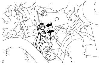
Tighten the 2 bolts.
- Torque:
- 78 N*m { 795 kgf*cm, 58 ft.*lbf }
-
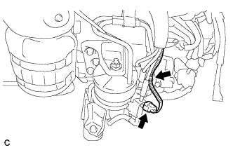
Connect the duty vacuum switching valve connector and clamp.
-
Install the 5 hole plugs.
-
-
REMOVE ENGINE HANGERS
-
Remove the 4 bolts and 2 engine hangers.
-
-
INSTALL POWER STEERING LINK ASSEMBLY
-
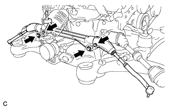
Install the power steering link assembly with the 2 bolts and 2 nuts.
- Torque:
- 70 N*m { 713 kgf*cm, 51 ft.*lbf }
Note
-
Make sure to tighten the bolts starting from the left side of the vehicle.
-
Because the nut has its own stopper, do not turn the nut. Tighten the bolt with the nut fixed.
-
-
INSTALL FRONT STABILIZER BAR WITH FRONT STABILIZER LINK ASSEMBLY
-
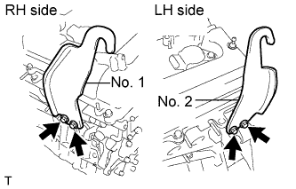
INSTALL NO. 1 FRONT STABILIZER BRACKET LH
-
Install the No. 1 front stabilizer bracket LH to the front frame assembly with the 2 bolts.
- Torque:
- 29 N*m { 296 kgf*cm, 21 ft.*lbf }
-
-
INSTALL NO. 1 FRONT STABILIZER BRACKET RH
Tech Tips
Perform the same procedure as the LH side.
-
INSTALL ENGINE ASSEMBLY WITH TRANSAXLE
Tech Tips
Install engine assembly with trans axle Click here.