FRONT SHOCK ABSORBER INSTALLATION
-
INSTALL FRONT COIL SPRING LOWER INSULATOR
-
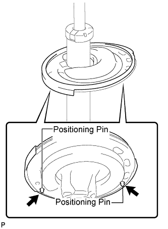
Install the front coil spring lower insulator to the front shock absorber.
Note
Make sure that the positioning pins on the front coil spring lower insulator are inserted into the holes in the front shock absorber.
-
-
INSTALL FRONT SPRING BUMPER
-
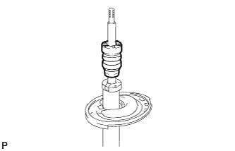
Install the front spring bumper to the front shock absorber.
-
-
INSTALL FRONT COIL SPRING
-
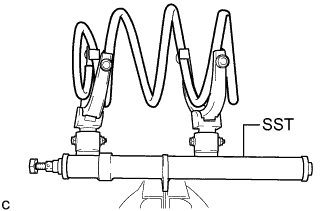
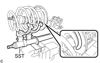
Attach SST to the front coil spring and secure it in a vise.
- SST
- 09727-30021 ( 09727-00010, 09727-00031 )
- 09727-00050
-
Attach the arm of SST to the diameter of the front coil spring.
CAUTION:
-
Make sure that the front coil spring is installed so that the distance between the upper and lower hooks of SST is at the maximum.
-
Make sure that the claws of the hooks are securely attached.
-
-
Using SST, compress the front coil spring.
CAUTION:
-
If the front coil spring bends during the compression, immediately stop the compression and reinstall SST.
-
Do not compress the spring until the coil springs contact each other.
-
Do not use an impact wrench. It will damage SST.
-
-
Install the front coil spring to the front shock absorber assembly.
Note
Make sure that the end of the front coil spring is positioned in the depression of the front lower coil spring insulator.
-
-
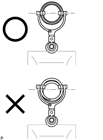
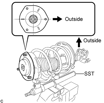
INSTALL FRONT COIL SPRING UPPER INSULATOR
-
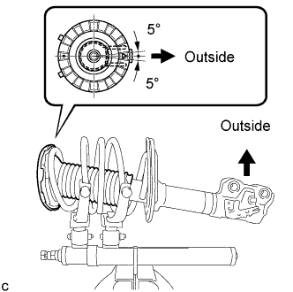
Install the front coil spring upper insulator as shown in the illustration.
Tech Tips
Any misalignment between the front shock absorber lower bracket and the alignment mark must be +/- 5°.
-
-
INSTALL FRONT COIL SPRING UPPER SEAT
-
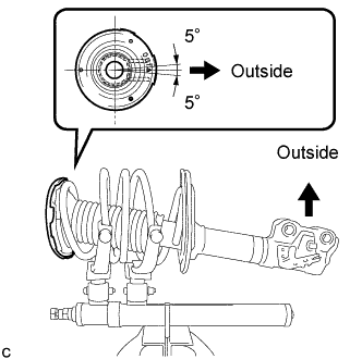
Install the front coil spring upper seat with the mark facing to the outside of the vehicle.
Tech Tips
Any misalignment between the front shock absorber lower bracket and the alignment mark must be +/- 5°.
-
-
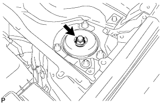
INSTALL FRONT SUSPENSION SUPPORT BEARING
-
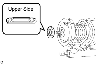
Install the front suspension support bearing as shown in the illustration.
-
-
INSTALL FRONT SUSPENSION SUPPORT SUB-ASSEMBLY
-
Install the front suspension support sub-assembly as shown in the illustration.
Tech Tips
Check that the slot on the piston rod and the slot on the front suspension support sub-assembly are aligned.
-
Temporarily tighten a new front support to front shock absorber nut.
-
-
INSTALL FRONT SHOCK ABSORBER WITH COIL SPRING
-
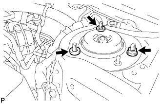
Install the front shock absorber with coil spring (upper side) with the nut and 2 spacers.
- Torque:
- 85 N*m { 866 kgf*cm, 63 ft.*lbf }
-
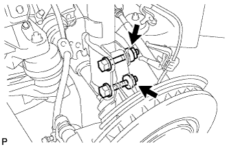
Install the front shock absorber with coil spring (lower side) to the steering knuckle and insert the 2 bolts and 2 nuts.
- Torque:
- 290 N*m { 2956 kgf*cm, 214 ft.*lbf }
Note
When installing the nuts, keep the bolts from rotating.
-
-
INSTALL FRONT STABILIZER LINK ASSEMBLY
-
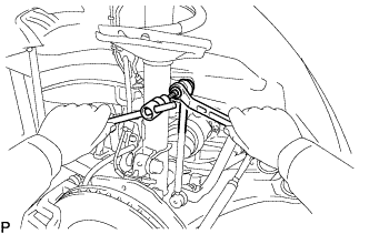
Install the front stabilizer link assembly to the front shock absorber with the nut.
- Torque:
- 74 N*m { 755 kgf*cm, 55 ft.*lbf }
Note
If the ball joint turns together with the nut, use a hexagon wrench (6 mm) to hold the stud bolt.
-
-
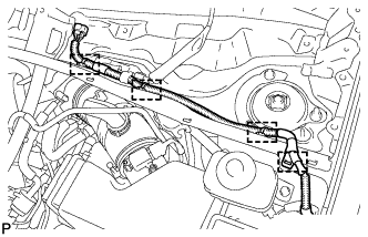
INSTALL FRONT SPEED SENSOR
-
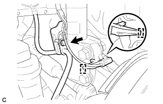
Install the front speed sensor and front flexible hose with the bolt.
- Torque:
- 19 N*m { 194 kgf*cm, 14 ft.*lbf }
Note
Do not twist the front speed sensor when installing it.
-
Install the clamp.
-
-
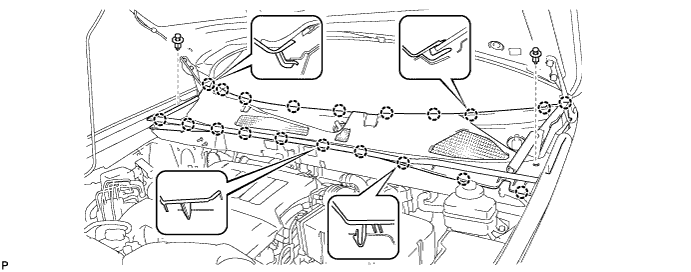
INSTALL OUTER COWL TOP PANEL SUB-ASSEMBLY
-
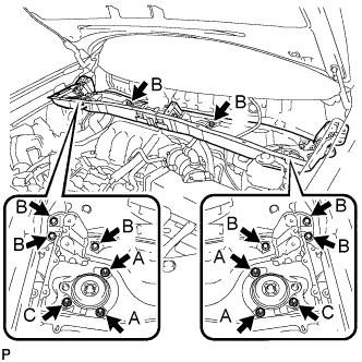
Install the outer cowl top panel sub-assembly with the 8 bolts and 6 nuts.
- Torque:
- Nut A
- 85 N*m { 866 kgf*cm, 63 ft.*lbf }
- Bolt B
- 8.8 N*m { 90 kgf*cm, 78 in.*lbf }
- Nut C
- 8.8 N*m { 90 kgf*cm, 78 in.*lbf }
-
Engage the 4 clamps.
-
-
FULLY TIGHTEN FRONT SUPPORT TO FRONT SHOCK ABSORBER NUT
-
Fully tighten the front support to front shock absorber nut.
- Torque:
- 70 N*m { 714 kgf*cm, 52 ft.*lbf }
-
-
INSTALL WINDSHIELD WIPER MOTOR AND LINK
-
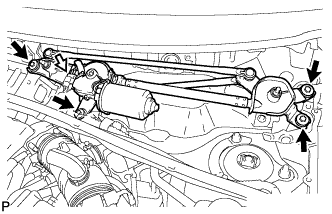
Install the windshield wiper motor and link assembly with the 4 bolts.
- Torque:
- 7.0 N*m { 71 kgf*cm, 62 in.*lbf }
-
Connect the connector.
-
-
INSTALL COWL TOP VENTILATOR LOUVER SUB-ASSEMBLY
-
Engage the 20 claws.
-
Install the cowl top ventilator louver sub-assembly with the 2 clips.
-
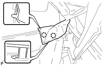
Engage the 2 claws and connect the front fender to cowl side seal LH.
-
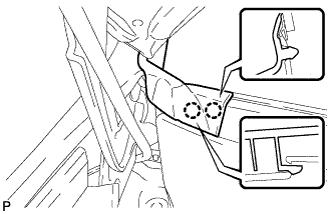
Engage the 2 claws and connect the front fender to cowl side seal RH.
-
-
INSTALL FRONT WIPER ARM AND BLADE ASSEMBLY RH
-
Operate the wiper and stop the windshield wiper motor at the automatic stop position.
-
When reinstalling:
-
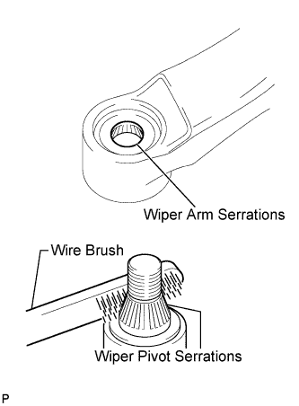
Clean the wiper arm serrations.
-
Clean the wiper pivot serrations with a wire brush.
-
-
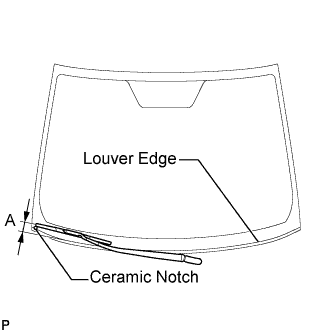
Install the front wiper arm and blade assembly RH with the nut to the position shown in the illustration.
- Torque:
- 24 N*m { 245 kgf*cm, 18 ft.*lbf }
Tech Tips
Hold the wiper arm by hand when tightening the nut.
Area Measurement A 25.6 mm (1.00 in.)
-
-
INSTALL FRONT WIPER ARM AND BLADE ASSEMBLY LH
-
Operate the wiper and stop the windshield wiper motor at the automatic stop position.
-
When reinstalling:
-
Clean the wiper arm serrations.
-
Clean the wiper pivot serrations with a wire brush.
-
-
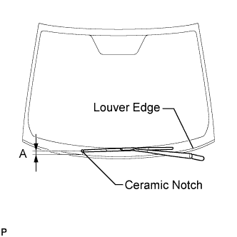
Install the front wiper arm and blade assembly LH with the nut to the position shown in the illustration.
- Torque:
- 24 N*m { 245 kgf*cm, 18 ft.*lbf }
Tech Tips
Hold the wiper arm by hand when tightening the nut.
Area Measurement A 31.9 mm (1.26 in.) -
Operate the front wipers while spraying washer fluid onto the windshield glass. Make sure that the front wipers function properly and the wipers do not come into contact with the vehicle body.
-
-
INSTALL FRONT WHEEL
- Torque:
- 103 N*m { 1050 kgf*cm, 76 ft.*lbf }
-
INSPECT AND ADJUST FRONT WHEEL ALIGNMENT
Inspect and adjust front wheel alignment Click here.