REAR WHEEL ALIGNMENT ADJUSTMENT
Note
If the wheel alignment has been adjusted, and if suspension or underbody components have been removed/installed or replaced, be sure to perform the following initialization procedure in order for the system to function normally:
-
Disconnect the cable from the negative battery terminal for more than 2 seconds.
-
Reconnect the cable to the negative battery terminal.
-
Perform zero point calibration of the yaw rate and acceleration sensor and test mode inspection.
Tech Tips
-
INSPECT TIRES
-
Inspect the tires Click here.
-
-
MEASURE VEHICLE HEIGHT
Note
-
Before inspecting the wheel alignment, adjust the vehicle height to the specified value.
-
Be sure to perform measurement on a level surface.
-
If it is necessary to go under the vehicle for measurement, confirm that the parking brake is applied and the vehicle is secured with chocks.
-
Bounce on the vehicle up and down at the corners to stabilize the suspension.
-
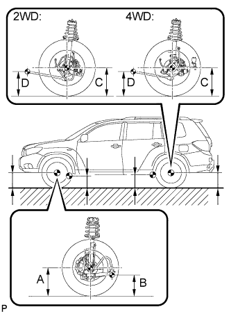
Measure the vehicle height.
Measuring points A Ground clearance of front wheel center B Ground clearance of No. 1 lower suspension arm bushing set bolt center C Ground clearance of rear wheel center D Ground clearance of strut rod set bolt center Vehicle height Model Front A - B Rear C - D 2WD 118.2 mm (4.65 in.) 34.9 mm (1.37 in.) 4WD 118.3 mm (4.66 in.) 33.8 mm (1.33 in.)
-
-
INSPECT TOE-IN
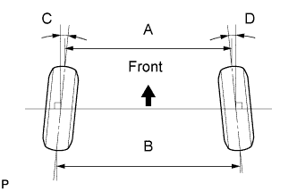
Toe-in Item Specified Condition Toe-in (2WD)
(total)
C + D: 0°10' +/- 0°12' (0.17° +/- 0.2°)
B - A: 3.0 +/- 2.0 mm (0.12 +/- 0.08 in.)
Toe-in (4WD)
(total)
C + D: 0°8' +/- 0°12' (0.14° +/- 0.2°)
B - A: 3.0 +/- 2.0 mm (0.12 +/- 0.08 in.)
If toe-in is not within the specified range, adjust it at the rear No. 2 suspension arms.
Tech Tips
Measure "B - A" only when "C + D" cannot be measured.
-
ADJUST TOE-IN (for 2WD)
-
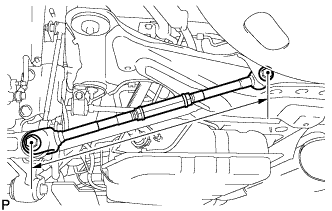
Measure the lengths of the right and left rear No. 2 suspension arms.
Standard difference 1.5 mm (0.06 in.) or less If the left-right difference is larger than 1.5 mm (0.06 in.), adjust it by following the procedures below.
-
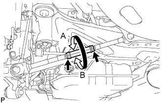
Loosen the 2 lock nuts.
-
If the length difference between the left and right rear No. 2 suspension arm assemblies is not within the specified range, adjust it by following the procedures below.
Tech Tips
-
Try to adjust toe-in to the center of the specified range.
-
One turn of each adjusting tube will adjust toe-in by approximately 11.1 mm (0.44 in.).
-
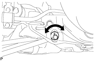
If the toe-in measurement is greater than the specified range, extend the shorter rear No. 2 suspension arm assembly by rotating the adjusting tube in the direction of arrow B in the illustration.
-
If the toe-in measurement is less than the specified range, shorten the longer rear No. 2 suspension arm assembly by rotating the adjusting tube in the direction of arrow A in the illustration.
-
Measure the toe-in.
-
-
Turn the right and left adjusting tubes by an equal amount to adjust toe-in.
-
Tighten the 2 lock nuts.
- Torque:
- 56 N*m { 571 kgf*cm, 41 ft.*lbf }
-
-
ADJUST TOE-IN (for 4WD)
-
Measure the distance between each wheel disc and the center of the toe-adjusting cam, and then confirm that left and right distances are the same.
Difference in the length of rear No. 2 suspension arms 1.0 mm (0.04 in.) or less If the left-right difference is larger than 1.0 mm (0.04 in.), adjust it by following the procedures below.
-
Loosen the toe-adjust cam set nuts.
-
Turn the adjust cams by an equal amount to adjust toe-in.
Tech Tips
-
Try to adjust toe-in to the center of the specified range.
-
The toe-in will change by the following amount corresponding to each graduation of the cam.
Approx. 3.3 mm (0.13 in.)
-
-
Tighten the toe-adjust cam set nuts.
- Torque:
- 100 N*m { 1019 kgf*cm, 74 ft.*lbf }
-
-
INSPECT CAMBER
- 2WD 4WD Right-left difference Camber -1°00' +/- 45' (-1.00° +/- 0.75°) -0°36' +/- 45' (-0.60° +/- 0.75°) 45' (0.75°) or less Tech Tips
Camber is not adjustable. If the measurement is not within the specified range, inspect the suspension parts for damage and/or wear, and replace them if necessary.
-
PLACE FRONT WHEELS FACING STRAIGHT AHEAD
-
DISCONNECT CABLE FROM NEGATIVE BATTERY TERMINAL
Note
When disconnecting the cable, some systems need to be initialized after the cable is reconnected Click here.
Tech Tips
Disconnect the cable from the negative battery terminal for more than 2 seconds.
-
CONNECT CABLE TO NEGATIVE BATTERY TERMINAL
Note
When disconnecting the cable, some systems need to be initialized after the cable is reconnected Click here.
-
PERFORM YAW RATE SENSOR ZERO POINT CALIBRATION
Tech Tips
Perform yaw rate sensor zero point calibration Click here.
-
CHECK STEERING ANGLE SENSOR ZERO POINT CALIBRATION
Tech Tips
Check steering angle sensor zero point calibration Click here.