If the wheel alignment has been adjusted, and if suspension or underbody components have been removed/installed or replaced, be sure to perform the following initialization procedure in order for the system to function normally:
-
Disconnect the cable from the negative battery terminal for more than 2 seconds.
-
Reconnect the cable to the negative battery terminal.
-
Perform zero point calibration of the yaw rate and acceleration sensor and test mode inspection.
- Click here
INSPECT TIRES
-
Inspect the tires (Click here).
-
- Click here
MEASURE VEHICLE HEIGHT
Note:
-
Before inspecting the wheel alignment, adjust the vehicle height to the specified value.
-
Be sure to perform measurement on a level surface.
-
If it is necessary to go under the vehicle for measurement, confirm that the parking brake is applied and the vehicle is secured with chocks.
-
Bounce on the vehicle up and down at the corners to stabilize the suspension.
-
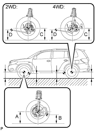
Measure the vehicle height.
Measuring points A Ground clearance of front wheel center B Ground clearance of No. 1 lower suspension arm bushing set bolt center C Ground clearance of rear wheel center D Ground clearance of strut rod set bolt center Vehicle height Model Front A - B Rear C - D 2WD 118.2 mm (4.65 in.) 34.9 mm (1.37 in.) 4WD 118.3 mm (4.66 in.) 33.8 mm (1.33 in.)
-
-
Click here
INSPECT TOE-IN
Toe-in Item Specified Condition Toe-in (2WD)
(total)
C + D: 0°10' +/- 0°12' (0.17° +/- 0.2°)
B - A: 3.0 +/- 2.0 mm (0.12 +/- 0.08 in.)
Toe-in (4WD)
(total)
C + D: 0°8' +/- 0°12' (0.14° +/- 0.2°)
B - A: 3.0 +/- 2.0 mm (0.12 +/- 0.08 in.)
If toe-in is not within the specified range, adjust it at the rear No. 2 suspension arms.
Tip:Measure "B - A" only when "C + D" cannot be measured.
- Click here
ADJUST TOE-IN (for 2WD)
-
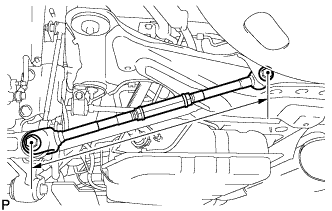
Measure the lengths of the right and left rear No. 2 suspension arms.
Standard difference 1.5 mm (0.06 in.) or less If the left-right difference is larger than 1.5 mm (0.06 in.), adjust it by following the procedures below.
-
Loosen the 2 lock nuts.
-
If the length difference between the left and right rear No. 2 suspension arm assemblies is not within the specified range, adjust it by following the procedures below.
Tip:
-
Try to adjust toe-in to the center of the specified range.
-
One turn of each adjusting tube will adjust toe-in by approximately 11.1 mm (0.44 in.).
-
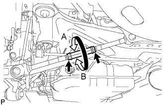
If the toe-in measurement is greater than the specified range, extend the shorter rear No. 2 suspension arm assembly by rotating the adjusting tube in the direction of arrow B in the illustration.
-
If the toe-in measurement is less than the specified range, shorten the longer rear No. 2 suspension arm assembly by rotating the adjusting tube in the direction of arrow A in the illustration.
-
Measure the toe-in.
-
-
Turn the right and left adjusting tubes by an equal amount to adjust toe-in.
-
Tighten the 2 lock nuts.
56 N*m 571 kgf*cm 41 ft.*lbf
-
- Click here
ADJUST TOE-IN (for 4WD)
-
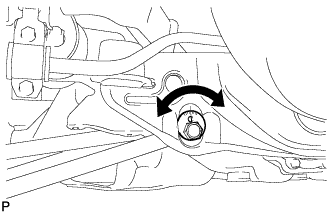
Measure the distance between each wheel disc and the center of the toe-adjusting cam, and then confirm that left and right distances are the same.
Difference in the length of rear No. 2 suspension arms 1.0 mm (0.04 in.) or less If the left-right difference is larger than 1.0 mm (0.04 in.), adjust it by following the procedures below.
-
Loosen the toe-adjust cam set nuts.
-
Turn the adjust cams by an equal amount to adjust toe-in.
Tip:
-
Try to adjust toe-in to the center of the specified range.
-
The toe-in will change by the following amount corresponding to each graduation of the cam.
Approx. 3.3 mm (0.13 in.)
-
-
Tighten the toe-adjust cam set nuts.
100 N*m 1019 kgf*cm 74 ft.*lbf
-
- Click here
INSPECT CAMBER
- 2WD 4WD Right-left difference Camber -1°00' +/- 45' (-1.00° +/- 0.75°) -0°36' +/- 45' (-0.60° +/- 0.75°) 45' (0.75°) or less Tip:Camber is not adjustable. If the measurement is not within the specified range, inspect the suspension parts for damage and/or wear, and replace them if necessary.
- Click here
PLACE FRONT WHEELS FACING STRAIGHT AHEAD
- Click here
DISCONNECT CABLE FROM NEGATIVE BATTERY TERMINAL
Note:When disconnecting the cable, some systems need to be initialized after the cable is reconnected (Click here).
Tip:Disconnect the cable from the negative battery terminal for more than 2 seconds.
- Click here
CONNECT CABLE TO NEGATIVE BATTERY TERMINAL
Note:When disconnecting the cable, some systems need to be initialized after the cable is reconnected (Click here).
- Click here
PERFORM YAW RATE SENSOR ZERO POINT CALIBRATION
Tip:Perform yaw rate sensor zero point calibration (Click here).
- Click here
CHECK STEERING ANGLE SENSOR ZERO POINT CALIBRATION
Tip:Check steering angle sensor zero point calibration (Click here).