FRONT AXLE HUB REMOVAL
-
REMOVE FRONT WHEEL
-
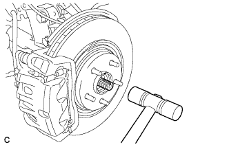
REMOVE FRONT AXLE HUB NUT
-
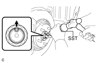
Using SST and a hammer, release the staked part of the front axle hub nut.
- SST
- 09930-00010
Note
Loosen the staked part of the nut completely, otherwise the threads of the drive shaft may be damaged.
-
While applying the brakes, remove the front axle hub nut.
-
-
SEPARATE FRONT SPEED SENSOR
-
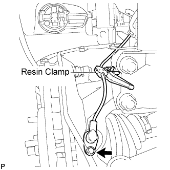
Remove the bolt and resin clamp, and separate the front speed sensor.
-
-
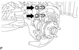
SEPARATE FRONT DISC BRAKE CALIPER ASSEMBLY
-
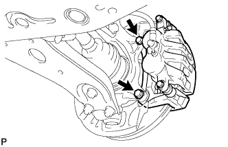
Remove the 2 bolts and separate the front disc brake caliper assembly.
Note
Use wire or an equivalent tool to keep the front disc brake caliper assembly from hanging down by the flexible hose.
-
-
REMOVE FRONT DISC
-
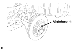
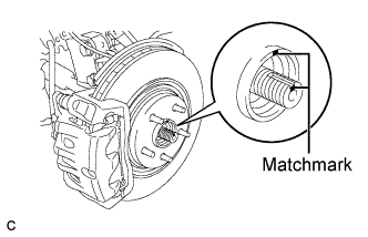
Remove the front disc.
Tech Tips
Put matchmarks on the disc and the axle hub.
-
-
SEPARATE TIE ROD ASSEMBLY
-
Remove the cotter pin and the nut.
-
Install SST to the tie rod end.
- SST
- 09960-20010 ( 09961-02060 )
Note
Make sure that the upper ends of the tie rod end and SST are aligned.
-
Using SST, separate the tie rod end from the steering knuckle.
- SST
- 09960-20010 ( 09961-02010 )
Note
-
When securing SST to the steering knuckle, be sure to tighten the string of SST to prevent it from falling.
-
Install SST so that A and B are parallel.
-
Be sure to place the wrench on the part indicated in the illustration.
-
Do not damage the front disc brake dust cover.
-
Do not damage the ball joint dust cover.
-
Do not damage the steering knuckle.
-
-
SEPARATE FRONT LOWER SUSPENSION ARM
-
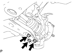
Remove the bolt and 2 nuts, and separate the front lower suspension arm from the front lower ball joint.
-
-
SEPARATE FRONT DRIVE SHAFT ASSEMBLY
-
Put matchmarks on the front drive shaft assembly and the front axle hub sub-assembly.
Note
Do not punch the marks.
-
Using a plastic hammer, separate the front drive shaft assembly from the front axle assembly.
Note
Be careful not to damage the drive shaft boot and speed sensor rotor.
-
-
REMOVE FRONT AXLE ASSEMBLY
-
Remove the 2 bolts, 2 nuts and front axle assembly.
Note
When removing the nuts, keep the bolts from rotating.
-
-
REMOVE FRONT LOWER BALL JOINT
-
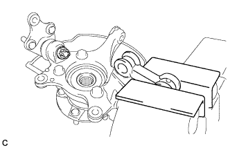
Secure the front axle assembly in a vise using aluminum plates.
Note
When using a vise, do not overtighten it.
-
Remove the cotter pin and nut.
-
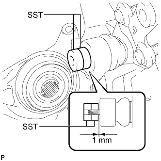
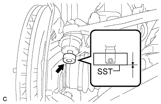
Install SST to the front lower ball joint as shown in the illustration.
- SST
- 09960-20010 ( 09961-02050, 09961-02050 )
Note
Check that the clearance measurement between SST and the front axle assembly is 1 mm (0.04 in.).
-
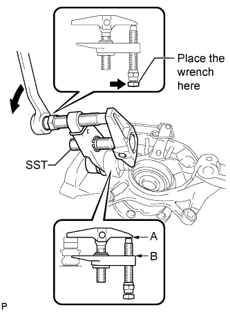
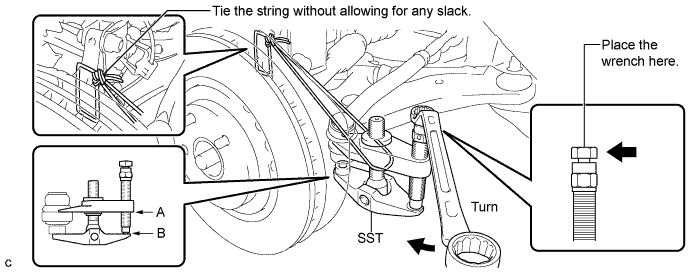
Using SST, remove the front lower ball joint from the front axle assembly as shown in the illustration.
- SST
- 09960-20010 ( 09961-02010, 09961-02050, 09961-02050 )
Note
-
Install SST so that A and B are parallel.
-
Be sure to place a wrench on the part indicated in the illustration.
-
Do not damage the front lower ball joint dust cover.
-
-
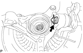
REMOVE NO. 1 FRONT WHEEL BEARING DUST DEFLECTOR
-
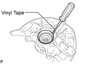
Using a screwdriver with its tip wrapped with vinyl tape, remove the No. 1 front wheel bearing dust deflector.
Note
Be careful not to damage the steering knuckle.
-
-
REMOVE FRONT AXLE HUB HOLE SNAP RING
-
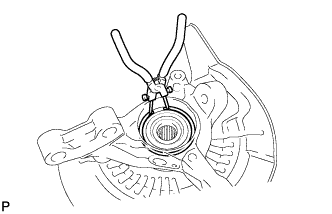
Using snap ring pliers, remove the front axle hub hole snap ring.
-
-
REMOVE FRONT AXLE HUB SUB-ASSEMBLY
-
Hold the front axle assembly between aluminium plates in a vise.
Note
Do not overtighten the vise.
-
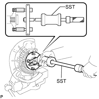
Using SST, remove the front axle hub sub-assembly.
- SST
- 09520-00031
-
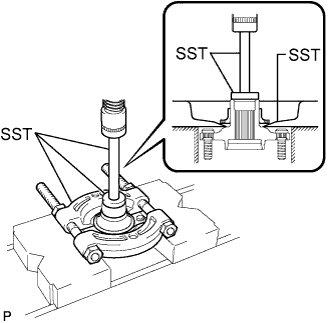
Using SST and a press, remove the bearing inner race (outside) from the front axle hub sub-assembly.
- SST
- 09555-55010
- 09950-60010 ( 09951-00430 )
- 09950-70010 ( 09951-07100 )
Note
Be careful not to drop the front axle hub sub-assembly.
-
-
REMOVE FRONT DISC BRAKE DUST COVER
-
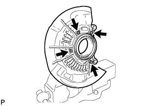
Remove the 4 bolts and front disc brake dust cover from the steering knuckle.
-
-
REMOVE FRONT AXLE HUB BEARING
-
Place the bearing inner race (outside) on the front axle hub bearing.
-
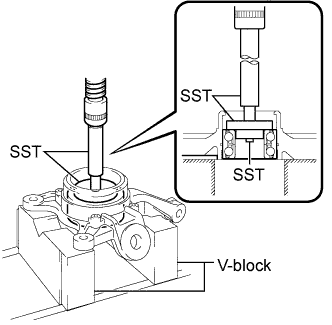
Using SST, V-blocks and a press, remove the front axle hub bearing from the steering knuckle.
- SST
- 09950-60010 ( 09951-00430, 09952-06010 )
- 09950-70010 ( 09951-07100 )
- 09950-60020 ( 09951-00750 )
Note
Keep the steering knuckle level.
-