REAR DIFFERENTIAL CARRIER ASSEMBLY INSPECTION
-
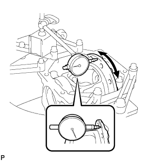
INSPECT RUNOUT OF DIFFERENTIAL RING GEAR
-
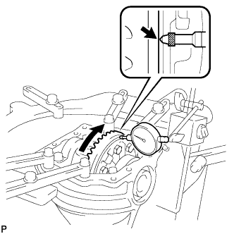
Using a dial indicator, check the runout of the differential ring gear.
Maximum runout 0.07 mm (0.0028 in.) Check that there is no damage to the differential case. If the differential case is damaged, replace it.
-
-
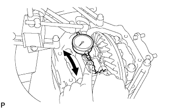
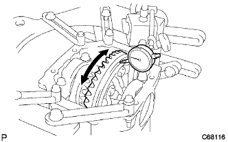
INSPECT DIFFERENTIAL RING GEAR BACKLASH
-

Using a dial indicator, check the backlash of the differential ring gear.
Backlash 0.13 to 0.18 mm (0.0051 to 0.0071 in.) If the backlash is not within the specification, adjust the side bearing preload or repair as necessary.
-
-
INSPECT DIFFERENTIAL PINION AND SIDE GEAR
-
Using a dial indicator, check the backlash of the differential side gear while holding one of the pinion gears toward the differential case assembly.
Backlash 0.05 to 0.20 mm (0.0020 to 0.0079 in.) If the backlash is not within the specification, install the 2 differential side gear thrust washers of different thicknesses.
Tech Tips
Measure the backlash of the differential side gear with the rear differential pinion shaft installed.
-
-
INSPECT RUNOUT OF REAR DRIVE PINION COMPANION FLANGE SUB-ASSEMBLY
-
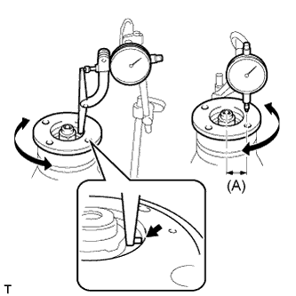
Using a dial indicator, measure the runout of the rear drive pinion companion flange sub-assembly vertically and horizontally.
(A) 30 mm (1.18 in.) Maximum runout 0.10 mm (0.0039 in.) If the runout is greater than the maximum value, replace the companion flange sub-assembly.
-
-
INSPECT DIFFERENTIAL DRIVE PINION PRELOAD
-
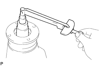
Using a torque wrench, measure the preload of the differential drive pinion.
Drive pinion preload (Initial) Item Preload New bearing 1.1 to 1.7 N*m (11.2 to 17.3 kgf*cm, 9.7 to 15.0 in.*lbf) Reused bearing 0.6 to 0.9 N*m (6.1 to 9.2 kgf*cm, 5.3 to 8.0 in.*lbf) If the preload is not within the specified range, adjust the total preload or repair as necessary.
-
-
INSPECT TOTAL PRELOAD
-
Using a torque wrench, measure the total preload.
Total preload (Initial) Drive pinion preload plus 0.3 to 0.5 N*m (3.1 to 5.1 kgf*cm, 2.7 to 4.4 in.*lbf) If the preload is not within the specified range, adjust the total preload or repair as necessary.
-
-
INSPECT DIFFERENTIAL CASE ASSEMBLY
-
Install the rear differential case to the rear differential carrier sub-assembly.
-
Install the right and left rear differential bearing caps with the 4 bolts.
- Torque:
- 79 N*m { 800 kgf*cm, 58 ft.*lbf }
-
Using a dial indicator, measure the differential case runout.
Maximum runout 0.07 mm (0.0028 in.) Tech Tips
If the runout is greater than the maximum, replace the differential drive pinion, differential ring gear and rear differential case.
-
Remove the rear differential case.
-
-
INSPECT DIFFERENTIAL RING GEAR
Tech Tips
Perform this procedure only if the runout of the differential ring gear exceeds the specified maximum value.
-
Install the rear differential case to the rear differential carrier sub-assembly, and install the 2 rear differential side gear shaft plate washers so that there is no play in the bearing.
-
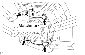
Align the matchmarks on the bearing cap and differential carrier, and install the 2 bearing caps.
Note
Make sure the right and left bearing caps are not interchanged.
-
Tighten both rear differential bearing caps with the 4 bolts.
- Torque:
- 79 N*m { 800 kgf*cm, 58 ft.*lbf }
-
Using a dial indicator, measure the runout of the differential ring gear.
Maximum runout 0.07 mm (0.0028 in.) If the runout is greater than the maximum value, replace the differential case assembly with a new one.
-
Remove the 2 rear differential bearing caps, 2 rear differential side gear shaft plate washers and differential case assembly.
-
-
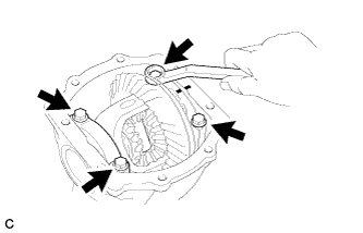
INSPECT TOOTH CONTACT BETWEEN RING GEAR AND DRIVE PINION
-
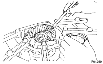
Coat 3 or 4 teeth at 3 different positions on the differential ring gear with Prussian blue.
-
Hold the rear drive pinion companion flange sub-assembly firmly and rotate the differential ring gear in both directions.
-
Inspect the tooth contact pattern.
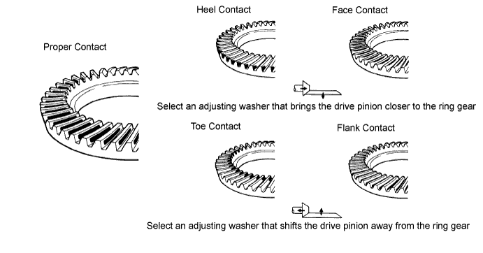
If the teeth are not contacting properly, use the following table to select a proper washer for correction.
Washer thickness Thickness mm (in.) Thickness mm (in.) Thickness mm (in.) 2.26 to 2.28 (0.0890 to 0.0898) 2.41 to 2.43 (0.0949 to 0.0957) 2.56 to 2.58 (0.1008 to 0.1016) 2.29 to 2.31 (0.0902 to 0.0909) 2.44 to 2.46 (0.0961 to 0.0969) 2.59 to 2.61 (0.1020 to 0.1028) 2.32 to 2.34 (0.0913 to 0.0921) 2.47 to 2.49 (0.0972 to 0.0980) 2.62 to 2.64 (0.1031 to 0.1039) 2.35 to 2.37 (0.0925 to 0.0933) 2.50 to 2.52 (0.0984 to 0.0992) 2.65 to 2.67 (0.1043 to 0.1051) 2.38 to 2.40 (0.0937 to 0.0945) 2.53 to 2.55 (0.0996 to 0.1004) 2.68 to 2.70 (0.1055 to 0.1063)
-