REAR DIFFERENTIAL CARRIER ASSEMBLY REASSEMBLY
-
INSTALL REAR DIFFERENTIAL PINION SHAFT
-
Install the 2 No. 1 rear differential side gear thrust washers to the 2 differential side gears.
-
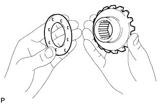
Install the 2 differential side gears, 2 differential pinion gears, 2 rear differential pinion thrust washers and rear differential pinion shaft to the rear differential case.
Tech Tips
Align the holes of the rear differential case and rear differential pinion shaft.
-
-
ADJUST DIFFERENTIAL PINION GEAR BACKLASH
-
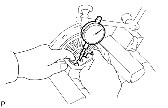
Measure the differential side gear backlash while holding one of the differential pinion gears toward the rear differential case.
Backlash 0.05 to 0.20 mm (0.0020 to 0.0079 in.) If the backlash is not within the specification, install the 2 No. 1 rear differential side gear thrust washers of different thicknesses.
Tech Tips
Refer to the following table to select 2 No. 1 rear differential side gear thrust washers.
Thrust washer thickness Thickness mm (in.) Thickness mm (in.) 0.87 to 0.93 (0.0343 to 0.0366) 1.18 to 1.22 (0.0465 to 0.0480) 0.93 to 0.97 (0.0366 to 0.0382) 1.23 to 1.27 (0.0484 to 0.0500) 0.98 to 1.02 (0.0386 to 0.0402) 1.28 to 1.32 (0.0504 to 0.0520) 1.03 to 1.07 (0.0406 to 0.0421) 1.33 to 1.37 (0.0524 to 0.0539) 1.08 to 1.12 (0.0425 to 0.0441) 1.38 to 1.42 (0.0543 to 0.0559) 1.13 to 1.17 (0.0445 to 0.0461) -
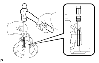
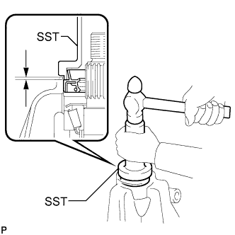
Using a pin punch (5 mm) and a hammer, install the rear differential pinion shaft straight pin through the differential case and hole of the rear differential pinion shaft.
-
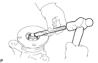
Using a chisel and a hammer, stake the outside of the rear differential case pin hole.
-
-
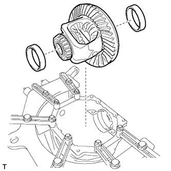
INSTALL DIFFERENTIAL RING GEAR
-
Clean the contact surfaces of the rear differential case and differential ring gear.
-
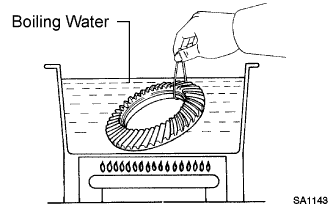
Heat the differential ring gear to approx. 100°C (212°F) in boiling water.
-
Carefully take the differential ring gear out of the boiling water.
-
After the moisture on the differential ring gear has completely evaporated, quickly install the differential ring gear to the rear differential case.
-
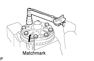
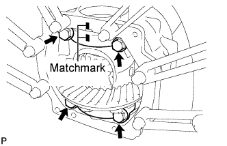
Align the matchmarks on the differential ring gear and rear differential case.
-
Temporarily install 4 new rear differential ring gear set bolt lock plates and the 8 bolts.
-
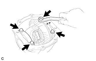
After the differential ring gear cools down enough, tighten the 8 bolts uniformly.
- Torque:
- 97 N*m { 985 kgf*cm, 71 ft.*lbf }
Tech Tips
Tighten the bolts, in diagonal order, a little at a time until they are all tightened.
-
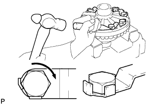
Using a chisel and a hammer, stake the 4 rear differential ring gear set bolt lock plates.
-
Stake one claw so that it is flush against the flat surface of the bolt.
Tech Tips
If the bolt starts loosening, the bolt head will act as a stopper.
-
-
-
INSTALL REAR DIFFERENTIAL CASE BEARING (for RH Side)
-
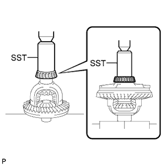
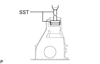
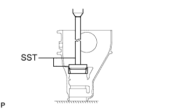
Using SST and a press, install the rear differential case bearing to the rear differential case.
- SST
- 09636-20010
-
-
INSTALL REAR DIFFERENTIAL CASE BEARING (for LH Side)
-
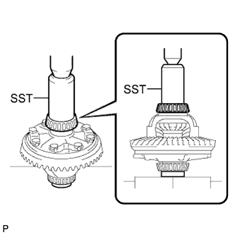
Using SST and a press, install the rear differential case bearing to the rear differential case.
- SST
- 09636-20010
-
-
INSPECT RUNOUT OF DIFFERENTIAL RING GEAR
-
Install the rear differential case to the rear differential carrier sub-assembly, and install the 2 rear differential side gear shaft plate washers so that there is no play in the bearing.
-
Align the matchmarks on the bearing cap and differential carrier, and install the 2 bearing caps.
Note
Make sure the right and left bearing caps are not interchanged.
-
Tighten both rear differential bearing caps with the 4 bolts.
- Torque:
- 79 N*m { 800 kgf*cm, 58 ft.*lbf }
-
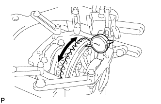
Using a dial indicator, measure the runout of the differential ring gear.
Maximum runout 0.07 mm (0.0028 in.) If the runout exceeds the specified maximum value, remove the ring gear and check the runout of the differential case.
-
Remove the 2 rear differential bearing caps, 2 rear differential side gear shaft plate washers and differential case assembly.
-
-
INSTALL REAR DRIVE PINION FRONT TAPERED ROLLER BEARING
-
Using SST and a press, install the rear drive pinion front tapered roller bearing (outer race) to the rear differential carrier sub-assembly.
- SST
- 09950-60010 ( 09951-00620 )
- 09950-70010 ( 09951-07150 )
-
-
INSTALL REAR DRIVE PINION REAR TAPERED ROLLER BEARING
-
Using SST and a press, install the rear drive pinion rear tapered roller bearing (outer race) to the rear differential carrier sub-assembly.
- SST
- 09950-60020 ( 09951-00710 )
- 09950-70010 ( 09951-07150 )
-
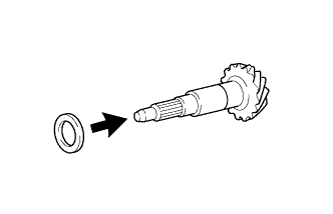
Install the rear differential drive pinion plate washer to the differential drive pinion.
-
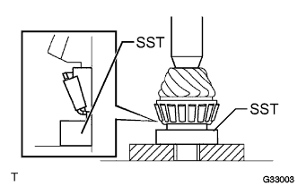
Using SST and a press, install the rear drive pinion rear tapered roller bearing to the differential drive pinion.
- SST
- 09506-30012
-
-
ADJUST DIFFERENTIAL DRIVE PINION PRELOAD
-
Install the differential drive pinion and rear drive pinion front tapered roller bearing.
Note
Assemble the rear differential drive pinion bearing spacer and rear differential carrier oil seal after adjusting the gear contact pattern.
-
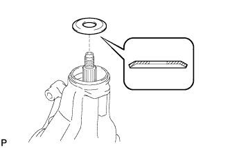
Install the rear differential drive pinion oil slinger to the differential drive pinion.
-
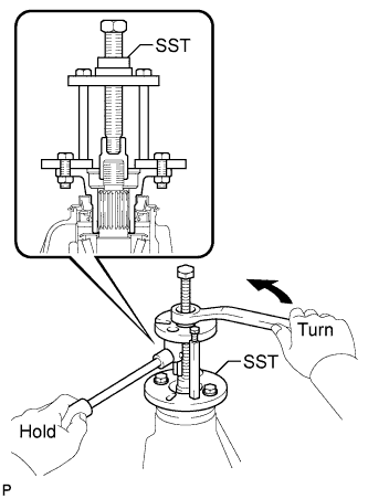
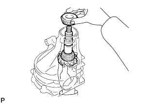
Using SST, install the rear drive pinion companion flange sub-assembly.
- SST
- 09950-30012 ( 09951-03010, 09953-03010, 09954-03010, 09955-03030, 09956-03020 )
-
Coat the threads of a new rear drive pinion nut with hypoid gear oil.
-
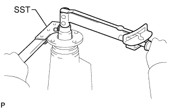
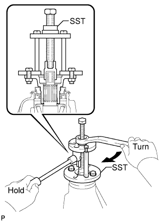
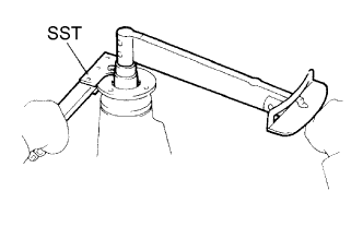
Using SST to hold the rear drive pinion companion flange sub-assembly, tighten the rear drive pinion nut.
- SST
- 09330-00021
- Torque:
- 108 N*m { 1100 kgf*cm, 80 ft.*lbf }
Note
-
Tighten the rear drive pinion nut a little at a time, being careful not to overtighten it.
-
Apply hypoid gear oil to the rear drive pinion nut.
-
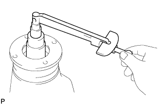
Using a torque wrench, measure the drive pinion preload.
Drive pinion preload (Initial) Item Preload New bearing 1.1 to 1.7 N*m (11.2 to 17.3 kgf*cm, 9.7 to 15.0 in.*lbf) Reused bearing 0.6 to 0.9 N*m (6.1 to 9.2 kgf*cm, 5.3 to 8.0 in.*lbf)
-
-
INSTALL REAR DIFFERENTIAL CASE
-
Place the 2 rear differential case bearings (outer races) on their respective bearings. Make sure the right and left races are not interchanged.
-
-
ADJUST DIFFERENTIAL RING GEAR BACKLASH
-
Install the right and left bearing caps with the 4 bolts.
- Torque:
- 79 N*m { 800 kgf*cm, 58 ft.*lbf }
Tech Tips
-
When using a new rear differential case bearing, select a rear differential side gear shaft plate washer which is thinner than the removed one.
-
If the side bearing is reused, select a rear differential side gear shaft plate washer of the same thickness as the removed one.
-
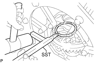
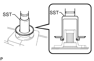
Using SST and a plastic hammer, drive in the rear differential side gear shaft plate washer.
- SST
- 09504-22011
-
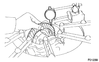
Set a dial indicator perpendicular to the end of the differential ring gear face.
-
While holding the rear drive pinion companion flange sub-assembly, rotate the differential ring gear and measure the backlash.
Backlash 0.13 to 0.18 mm (0.0051 to 0.0071 in.) Note
Measure the backlash at 3 points or more on the differential ring gear periphery.
If the measured value is out of the specified range, select a proper rear differential side gear shaft plate washer so that the backlash of the differential ring gear is within the specified range, and install the washer to the differential ring gear back side.
Washer thickness Thickness mm (in.) Thickness mm (in.) Thickness mm (in.) 2.21 to 2.23 (0.0870 to 0.0878) 2.57 to 2.59 (0.1012 to 0.1020) 2.93 to 2.95 (0.1154 to 0.1161) 2.24 to 2.26 (0.0882 to 0.0890) 2.60 to 2.62 (0.1024 to 0.1030) 2.96 to 2.98 (0.1165 to 0.1173) 2.27 to 2.29 (0.0894 to 0.0902) 2.63 to 2.65 (0.1035 to 0.1043) 2.99 to 3.01 (0.1177 to 0.1185) 2.30 to 2.32 (0.0906 to 0.0913) 2.66 to 2.68 (0.1047 to 0.1055) 3.02 to 3.04 (0.1189 to 0.1197) 2.33 to 2.35 (0.0917 to 0.0925) 2.69 to 2.71 (0.1059 to 0.1067) 3.05 to 3.07 (0.1201 to 0.1209) 2.36 to 2.38 (0.0929 to 0.0937) 2.72 to 2.74 (0.1071 to 0.1079) 3.08 to 3.10 (0.1213 to 0.1220) 2.39 to 2.41 (0.0941 to 0.0949) 2.75 to 2.77 (0.1083 to 0.1091) 3.11 to 3.13 (0.1224 to 0.1232) 2.42 to 2.44 (0.0953 to 0.0961) 2.78 to 2.80 (0.1094 to 0.1102) 3.14 to 3.16 (0.1236 to 0.1244) 2.45 to 2.47 (0.0965 to 0.0972) 2.81 to 2.83 (0.1106 to 0.1114) 3.17 to 3.19 (0.1248 to 0.1256) 2.48 to 2.50 (0.0976 to 0.0984) 2.84 to 2.86 (0.1118 to 0.1126) 3.20 to 3.22 (0.1260 to 0.1268) 2.51 to 2.53 (0.0988 to 0.0996) 2.87 to 2.89 (0.1130 to 0.1138) - 2.54 to 2.56 (0.1000 to 0.1008) 2.90 to 2.92 (0.1142 to 0.1150) -
-
-
ADJUST TOTAL PRELOAD
-
After adjusting the backlash of the differential ring gear, remove the teeth side rear differential side gear shaft plate washer.
-
Using a micrometer, measure the thickness of the removed rear differential side gear shaft plate washer.
-
Select a new rear differential side gear shaft plate washer which is 0.06 to 0.09 mm (0.0024 to 0.0035 in.) thicker than the removed one.
Tech Tips
Select a rear differential side gear shaft plate washer which can be pressed in 2/3 of the way with a finger.
-
Using SST and a plastic hammer, drive in the rear differential side gear shaft plate washer.
- SST
- 09504-22011
-
Align the matchmarks on the bearing cap and differential carrier, and install the 2 bearing caps.
Note
Make sure the right and left bearing caps are not interchanged.
-
Tighten both rear differential bearing caps with the 4 bolts.
- Torque:
- 79 N*m { 800 kgf*cm, 58 ft.*lbf }
-
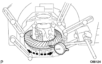
Set a dial indicator to the end of the differential ring gear face.
-
While holding the rear drive pinion companion flange sub-assembly, rotate the differential ring gear and measure the backlash.
Backlash 0.13 to 0.18 mm (0.0051 to 0.0071 in.) -
If the measured value is out of the specified range, adjust it by increasing or decreasing the thickness of both right and left rear differential side gear shaft plate washers equally.
-
Using a torque wrench, measure the preload.
Total preload (Initial) Drive pinion preload plus 0.3 to 0.5 N*m (3.1 to 5.1 kgf*cm, 2.7 to 4.4 in.*lbf)
-
-
INSPECT TOOTH CONTACT BETWEEN RING GEAR AND DRIVE PINION
-
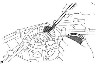
Coat 3 or 4 teeth at 3 different positions on the differential ring gear with Prussian blue.
-
Hold the rear drive pinion companion flange sub-assembly firmly and rotate the differential ring gear in both directions.
-
Inspect the tooth contact pattern.
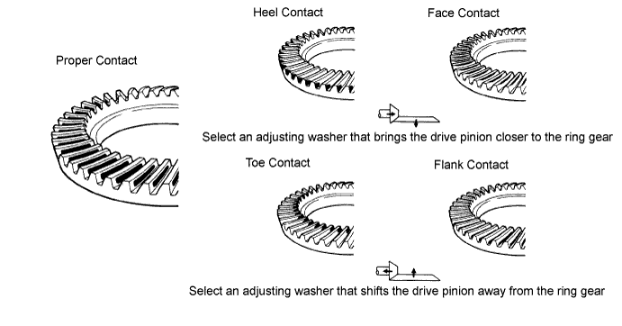
If the teeth are not contacting properly, use the following table to select a proper washer for correction.
Washer thickness Thickness mm (in.) Thickness mm (in.) Thickness mm (in.) 2.26 to 2.28 (0.0890 to 0.0898) 2.41 to 2.43 (0.0949 to 0.0957) 2.56 to 2.58 (0.1008 to 0.1016) 2.29 to 2.31 (0.0902 to 0.0909) 2.44 to 2.46 (0.0961 to 0.0969) 2.59 to 2.61 (0.1020 to 0.1028) 2.32 to 2.34 (0.0913 to 0.0921) 2.47 to 2.49 (0.0972 to 0.0980) 2.62 to 2.64 (0.1031 to 0.1039) 2.35 to 2.37 (0.0925 to 0.0933) 2.50 to 2.52 (0.0984 to 0.0992) 2.65 to 2.67 (0.1043 to 0.1051) 2.38 to 2.40 (0.0937 to 0.0945) 2.53 to 2.55 (0.0996 to 0.1004) 2.68 to 2.70 (0.1055 to 0.1063)
-
-
REMOVE REAR DRIVE PINION NUT
-
REMOVE REAR DRIVE PINION COMPANION FLANGE SUB-ASSEMBLY
-
Using SST, remove the rear drive pinion companion flange sub-assembly.
- SST
- 09950-30012 ( 09951-03010, 09953-03010, 09954-03010, 09955-03030, 09956-03020 )
-
-
REMOVE REAR DIFFERENTIAL DRIVE PINION OIL SLINGER
-
Remove the rear differential drive pinion oil slinger.
-
-
REMOVE REAR DRIVE PINION FRONT TAPERED ROLLER BEARING
-
Using SST, remove the rear drive pinion front tapered roller bearing from the differential drive pinion.
- SST
- 09556-22010
-
-
INSTALL REAR DIFFERENTIAL DRIVE PINION BEARING SPACER
-
Install a new rear differential drive pinion bearing spacer.
-
-
INSTALL REAR DRIVE PINION FRONT TAPERED ROLLER BEARING
-
Install the rear drive pinion front tapered roller bearing to the differential drive pinion.
-
-
INSTALL REAR DIFFERENTIAL DRIVE PINION OIL SLINGER
-
Install the rear differential drive pinion oil slinger to the differential drive pinion.
-
-
INSTALL REAR DIFFERENTIAL CARRIER OIL SEAL
-
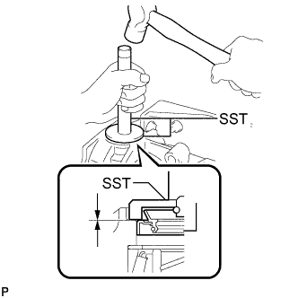
Using SST and a hammer, install a new rear differential carrier oil seal.
- SST
- 09554-22010
Oil seal driven in depth 2.0 +/- 0.3 mm (0.079 +/- 0.012 in.) -
Apply MP grease to the rear differential carrier oil seal lip.
-
-
INSTALL REAR DIFFERENTIAL DUST DEFLECTOR
-
Using SST and a press, install a new rear differential dust deflector.
- SST
- 09223-00010
Note
Be careful not to damage the rear differential dust deflector.
-
-
INSTALL REAR DRIVE PINION COMPANION FLANGE SUB-ASSEMBLY
-
Using SST, install the rear drive pinion companion flange sub-assembly to the differential drive pinion.
- SST
- 09950-30012 ( 09951-03010, 09953-03010, 09954-03010, 09955-03030, 09956-03020 )
-
Coat the threads of a new rear drive pinion nut with hypoid gear oil.
-
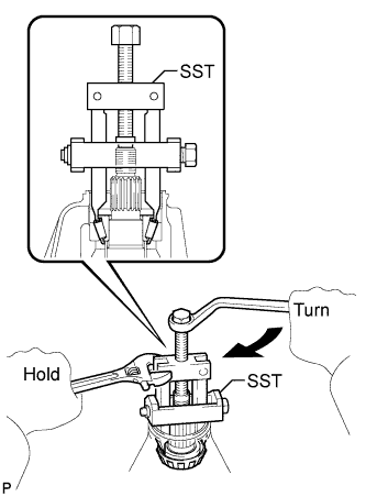
Using SST to hold the rear drive pinion companion flange sub-assembly, tighten the rear drive pinion nut.
- SST
- 09330-00021
- Torque:
- 108 N*m { 1100 kgf*cm, 80 ft.*lbf }
-
-
INSPECT DIFFERENTIAL DRIVE PINION PRELOAD
-
Using a torque wrench, measure the preload of the differential drive pinon.
Drive pinion preload (Initial) Item Preload New bearing 1.1 to 1.7 N*m (11.2 to 17.3 kgf*cm, 9.7 to 15.0 in.*lbf) Reused bearing 0.6 to 0.9 N*m (6.1 to 9.2 kgf*cm, 5.3 to 8.0 in.*lbf)
-
If the preload is greater than the specification, replace the rear differential drive pinion bearing spacer.
-
If the preload is less than the specification, replace the rear drive pinion nut and tighten it in several steps with 13 N*m (130 kgf*cm, 9 ft.*lbf) of torque at a time until the specified preload is reached.
Torque 235 N*m (2400 kgf*cm, 174 ft.*lbf) or less
-
If the torque exceeds the maximum while retightening the nut, replace the bearing spacer and repeat the preload adjusting procedure.
Note
Do not loosen the pinion nut to reduce the preload.
-
-
-
INSPECT TOTAL PRELOAD
-
Using a torque wrench, measure the preload.
Total preload (Initial) Drive pinion preload plus 0.3 to 0.5 N*m (3.1 to 5.1 kgf*cm, 2.7 to 4.4 in.*lbf)
-
-
INSPECT DIFFERENTIAL RING GEAR BACKLASH
-

Using a dial indicator, check the backlash of the differential ring gear.
Backlash 0.13 to 0.18 mm (0.0051 to 0.0071 in.) If the backlash is not within the specification, adjust the side bearing preload or repair as necessary.
-
-
INSPECT REAR DRIVE PINION COMPANION FLANGE SUB-ASSEMBLY
-
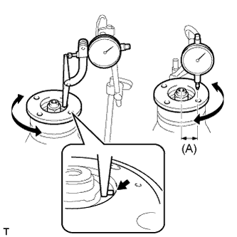
Using a dial indicator, measure the runout of the rear drive pinion companion flange sub-assembly vertically.
(A) 30 mm (1.18 in.) Maximum runout 0.10 mm (0.0039 in.)
-
-
INSTALL REAR DRIVE PINION NUT
-
Using a chisel and hammer, stake the rear drive pinion nut.
-
-
INSTALL REAR DIFFERENTIAL SIDE GEAR SHAFT OIL SEAL
-
Using SST and a hammer, install 2 new oil seals.
- SST
- 09550-00032
- 09950-70010 ( 09951-07200 )
Oil seal driven in depth 0 +/- 0.5 mm (0 +/- 0.019 in.) -
Apply MP grease to the oil seal lip.
-
-
INSTALL REAR DIFFERENTIAL BREATHER PLUG
-
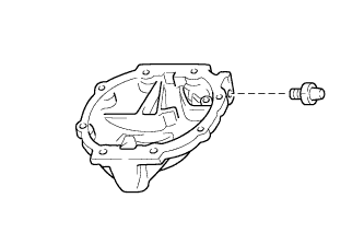
Install the rear differential breather plug to the rear differential carrier cover.
- Torque:
- 21 N*m { 210 kgf*cm, 15 ft.*lbf }
-
-
INSTALL REAR DIFFERENTIAL CARRIER COVER
-
Using gasoline or alcohol, remove any residual FIPG from the contact surfaces.
-
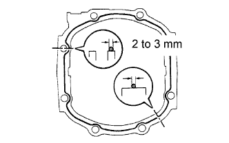
Apply FIPG to the rear differential carrier sub-assembly.
Tech Tips
-
FIPG should be applied 2 to 3 mm (0.08 to 0.12 in.) in diameter with no breaks.
-
Allow for an overlap of 10 mm (0.39 in.) or more between the start and end of FIPG application.
-
Install the rear differential carrier cover within 3 minutes after applying FIPG.
-
Do not add oil or drive the vehicle immediately after installing the cover, and leave it as is for at least an hour. Also, avoid rapid acceleration/deceleration for at least 12 hours.
-
-
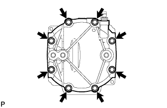
Install the rear differential carrier cover with the 8 bolts.
- Torque:
- 47 N*m { 475 kgf*cm, 34 ft.*lbf }
-