REAR DIFFERENTIAL SIDE GEAR SHAFT OIL SEAL REMOVAL
-
REMOVE REAR WHEEL
-
REMOVE REAR DIFFERENTIAL FILLER PLUG
-
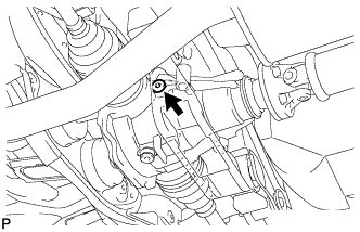
Using a hexagon wrench (10 mm), remove the rear differential filler plug and rear differential filler plug gasket.
-
-
REMOVE REAR DIFFERENTIAL DRAIN PLUG
-
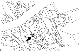
Using a hexagon wrench (10 mm), remove the rear differential drain plug and rear differential drain plug gasket, and drain the oil.
-
-
SEPARATE REAR SPEED SENSOR
-
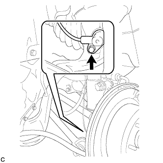
Remove the bolt and separate the rear speed sensor from the rear axle carrier sub-assembly.
Note
Keep the sensor tip and rear speed sensor installation hole free from foreign matter.
-
-
REMOVE REAR AXLE SHAFT NUT
-
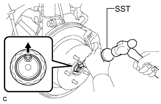
Using SST and a hammer, release the staked part of the rear axle shaft nut.
- SST
- 09930-00010
Note
Loosen the staked part of the nut completely, otherwise the threads of the drive shaft may be damaged.
-
While applying the brakes, remove the rear axle shaft nut.
-
-
SEPARATE REAR DISC BRAKE CALIPER ASSEMBLY
-
Remove the 2 bolts and separate the rear disc brake caliper assembly.
Note
Use wire or an equivalent tool to keep the brake caliper from hanging down by the flexible hose.
-
-
REMOVE REAR DISC
-
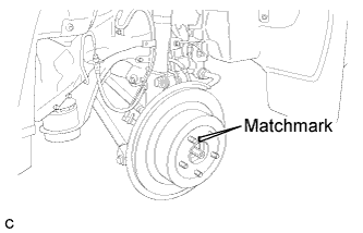
Put matchmarks on the rear disc and the axle hub.
-
Release the parking brake and remove the rear disc.
Tech Tips
If the disc cannot be removed easily, turn and press firmly the shoe adjuster until the wheel comes free.
-
-
REMOVE REAR AXLE HUB AND BEARING ASSEMBLY
-
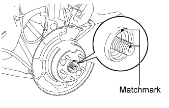
Put matchmarks on the drive shaft and axle hub.
Note
Do not punch the marks.
-
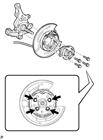
Remove the 4 bolts and the rear axle hub and bearing assembly.
Note
-
Do not rotate the drive shaft with the rear axle hub and bearing assembly removed.
-
Use wire or an equivalent tool to keep the parking brake assembly from hanging down by the parking brake cable assembly.
-
-
-
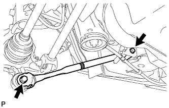
SEPARATE NO. 3 PARKING BRAKE CABLE ASSEMBLY
-
Remove the bolt and the nut, and separate the No. 3 parking brake cable assembly.
-
-
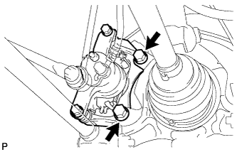
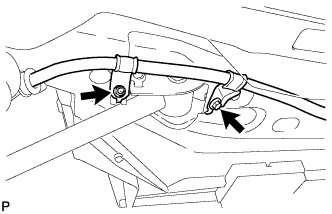
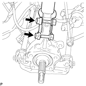
REMOVE REAR STRUT ROD ASSEMBLY
-
Remove the 2 bolts, the 2 nuts, and the rear strut rod assembly.
Note
Since stopper nuts are used, loosen the bolts.
-
-
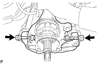
REMOVE REAR AXLE CARRIER SUB-ASSEMBLY
-
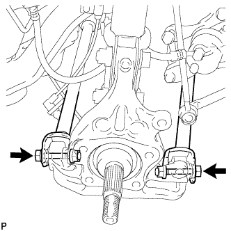
Loosen the 2 bolts.
Note
Since stopper nuts are used, loosen the bolts.
-
Remove the 2 bolts and 2 nuts, and separate the rear shock absorber with coil spring (lower side) from the rear axle carrier sub-assembly.
Note
-
Be careful not to damage the outboard joint boot.
-
Be careful not to damage the speed sensor rotor.
-
-
Remove the 2 bolts, the 2 nuts, and the rear axle carrier sub-assembly.
Note
-
Be careful not to damage the outboard joint boot.
-
Be careful not to damage the speed sensor rotor.
Tech Tips
Use wire or an equivalent tool to keep the rear drive shaft assembly from hanging down.
-
-
-
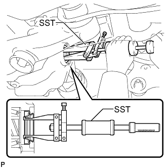
REMOVE REAR DRIVE SHAFT ASSEMBLY
-
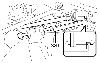
Using SST, remove the rear drive shaft assembly as shown in the illustration.
- SST
- 09520-01010
- 09520-24010 ( 09520-32040 )
Note
Remove the rear drive shaft assembly while keeping it level.
-
-
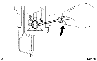
REMOVE REAR DRIVE SHAFT SNAP RING
-
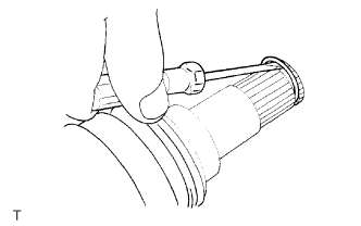
Using a screwdriver, remove the rear drive shaft snap ring.
-
-
REMOVE REAR DIFFERENTIAL SIDE GEAR SHAFT OIL SEAL
-
Using SST, remove the rear differential side gear shaft oil seal.
- SST
- 09308-00010
-