- Click here
INSTALL REAR DRIVE SHAFT ASSEMBLY
-
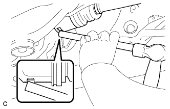
Align the shaft splines and install the rear drive shaft assembly with a brass bar and hammer.
Note:
-
Set the snap ring with the opening facing downward.
-
Be careful not to damage the oil seal, boot, or dust cover.
-
Install the drive shaft assembly while keeping it level.
-
-
- Click here
INSTALL REAR AXLE CARRIER SUB-ASSEMBLY LH
-
Temporarily install the the rear axle carrier sub-assembly with the 2 bolts and the 2 nuts.
Note:
-
Be careful not to damage the outboard joint boot.
-
Be careful not to damage the speed sensor rotor.
-
Prevent foreign matter from adhering to the speed sensor rotor.
-
-
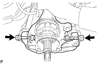
Install the rear axle carrier sub-assembly with the 2 bolts and the 2 nuts.
290 N*m 2956 kgf*cm 213 ft.*lbf Note:
-
Be careful not to damage the outboard joint boot.
-
Be careful not to damage the speed sensor rotor.
-
Prevent foreign matter from adhering to the speed sensor rotor.
-
Do not rotate the drive shaft with the rear axle hub and bearing assembly removed.
Tip:Insert the bolts from the rear side.
-
-
- Click here
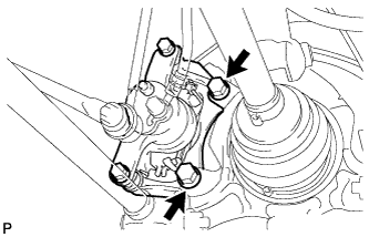
TEMPORARILY INSTALL REAR STRUT ROD ASSEMBLY
-
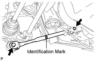
Check that the identification mark of the rear strut rod assembly is positioned on the inner side of the vehicle.
-
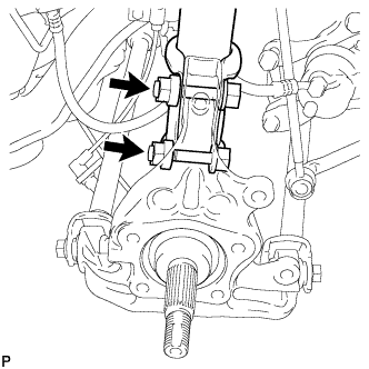
Temporarily install the rear strut rod assembly with the 2 bolts and the 2 nuts.
Note:Since stopper nuts are used, temporarily tighten the bolts.
-
- Click here
INSTALL REAR AXLE HUB AND BEARING ASSEMBLY LH
-
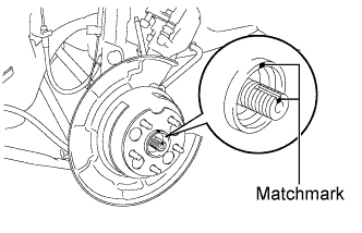
Align the matchmarks on the drive shaft and rear axle hub.
Note:Do not rotate the drive shaft.
-
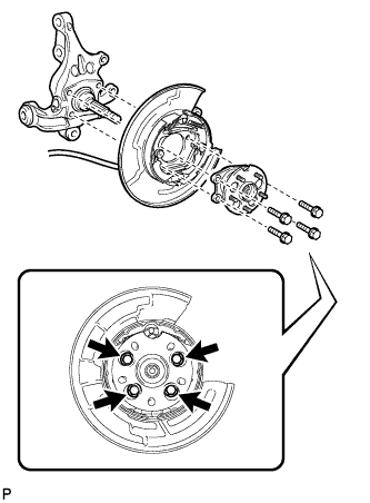
Install the parking brake assembly and the rear axle hub and bearing assembly with the 4 bolts.
75 N*m 764 kgf*cm 55 ft.*lbf Note:Do not twist the No. 3 parking brake cable assembly when installing it.
-
- Click here
INSTALL REAR DISC
-
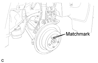
Align matchmarks and install the rear disc.
Note:When replacing the rear disc with a new one, select the installation position where the rear disc has minimal runout.
-
- Click here
INSTALL REAR DISC BRAKE CALIPER ASSEMBLY LH
-
Install the rear disc brake caliper assembly with the 2 bolts.
78 N*m 795 kgf*cm 57 ft.*lbf
-
- Click here
INSTALL REAR SPEED SENSOR LH
-
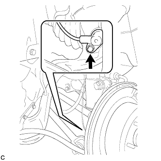
Install the rear speed sensor to the rear axle carrier sub-assembly with the bolt .
8.0 N*m 82 kgf*cm 71 in.*lbf Note:
-
Keep the rear speed sensor tip and sensor installation hole free from foreign matter.
-
To prevent interference with the bearing rotor, do not rotate the rear speed sensor body when inserting the rear speed sensor body or after inserting the rear speed sensor body.
-
Do not twist the rear speed sensor wire when installing.
-
-
- Click here
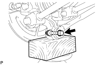
STABILIZE SUSPENSION
-
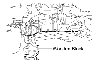
Jack up the rear axle carrier sub-assembly, placing a wooden block underneath to avoid damage. Apply load to the suspension so that the rear drive shaft assembly is positioned horizontally.
CAUTION:Do not jack up the rear axle carrier sub-assembly too high as the vehicle may fall.
Note:Do not bend the brake dust cover.
Tip:
-
If the rear drive shaft assembly cannot be positioned horizontally as shown in the illustration even when the rear axle carrier sub-assembly is jacked up, apply additional load to the vehicle such as by having a person sit in the rear seat.
-
Use the same procedure for the RH side and LH side.
-
-
- Click here
FULLY TIGHTEN REAR NO. 2 SUSPENSION ARM ASSEMBLY LH
-
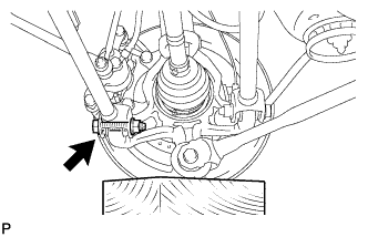
Fully tighten the rear No. 2 suspension arm assembly with the bolt and nut.
112 N*m 1141 kgf*cm 82 ft.*lbf Note:
-
Since a stopper nut is used, fully tighten the bolt.
-
The final torque must be applied under standard vehicle height conditions.
-
-
- Click here
FULLY TIGHTEN REAR NO. 1 SUSPENSION ARM ASSEMBLY LH
-
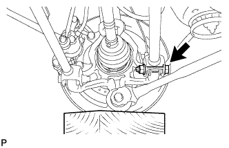
Fully tighten the rear No. 1 suspension arm assembly with the bolt and nut.
112 N*m 1141 kgf*cm 82 ft.*lbf Note:
-
Since a stopper nut is used, fully tighten the bolt.
-
The final torque must be applied under standard vehicle height conditions.
-
-
- Click here
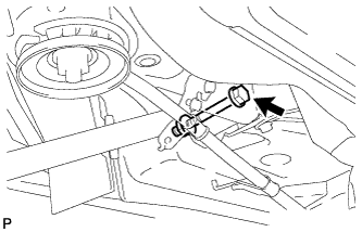
FULLY TIGHTEN REAR STRUT ROD ASSEMBLY
-
Fully tighten the bolt.
80 N*m 815 kgf*cm 59 ft.*lbf Note:
-
Since a stopper nut is used, fully tighten the bolt.
-
The final torque must be applied under standard vehicle height conditions.
-
-
Fully tighten the bolt.
80 N*m 815 kgf*cm 59 ft.*lbf Note:
-
Since a stopper nut is used, fully tighten the bolt.
-
The final torque must be applied under standard vehicle height conditions.
-
-
- Click here
INSTALL NO. 3 PARKING BRAKE CABLE ASSEMBLY
-
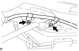
Install the No. 3 parking brake cable assembly with the bolt and the nut.
Bolt 39 N*m 397 kgf*cm 29 ft.*lbf Nut 6.0 N*m 61 kgf*cm 53 in.*lbf Note:Do not twist the No. 3 parking brake cable assembly when installing it.
-
- Click here
INSTALL REAR AXLE SHAFT NUT LH
-
Clean the threaded parts on the drive shaft and axle hub nut using a non-residue solvent.
Note:
-
Be sure to perform this work for a new drive shaft.
-
Keep the threaded parts free of oil and foreign objects.
-
-
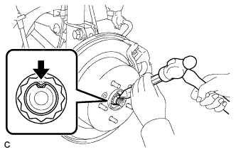
Install a new rear axle shaft nut.
294 N*m 2996 kgf*cm 216 ft.*lbf -
Using a chisel and hammer, stake the rear axle shaft nut.
-
- Click here
INSTALL REAR DIFFERENTIAL DRAIN PLUG
-
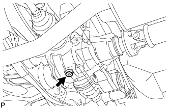
Using a hexagon wrench (10 mm), install the filler plug with a new gasket.
49 N*m 500 kgf*cm 36 ft.*lbf
-
- Click here
ADD DIFFERENTIAL OIL
-
Fill the rear differential carrier assembly with hypoid gear oil.
-
- Click here
INSPECT DIFFERENTIAL OIL
-
Stop the vehicle on a level place.
-
Remove the differential filler plug and gasket.
-
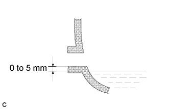
Check that the oil surface is within 5 mm (0.20 in.) of the lowest position of the inner surface of the differential filler plug opening.
Note:
-
Excessively large or small amounts of oil may cause trouble.
-
After replacing oil, drive the vehicle and check the oil level.
Tip:If necessary, fill the rear differential carrier with hypoid gear oil.
Oil grade Hypoid gear oil API GL-5 Recommended oil viscosity Above -18°C (0°F) : SAE 90 Below -18°C (0°F) : SAE 80W or 80W-90 Capacity 0.9 +/- 0.05 liters (0.95 +/- 0.05 US qts, 0.79 +/- 0.04 lmp. qts) -
-
Check for oil leakage when the oil level is low.
-
Install the differential filler plug and a new gasket.
49 N*m 500 kgf*cm 36 ft.*lbf
-
- Click here
INSTALL REAR DIFFERENTIAL FILLER PLUG
-
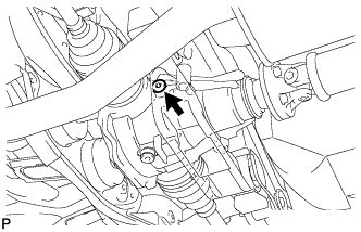
Using a hexagon wrench (10 mm), install the filler plug with a new gasket.
49 N*m 500 kgf*cm 36 ft.*lbf
-
- Click here
INSTALL REAR WHEEL
103 N*m 1050 kgf*cm 76 ft.*lbf - Click here
INSPECT AND ADJUST REAR WHEEL ALIGNMENT
Tip: - Click here
CHECK ABS SPEED SENSOR SIGNAL
Tip: