REAR DRIVE SHAFT (for 4WD) REASSEMBLY
-
INSTALL REAR DRIVE SHAFT DUST COVER
-
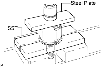
Using SST and a steel plate, install a new rear drive shaft dust cover.
- SST
- 09527-21011
Note
-
The rear drive shaft dust cover should be completely installed.
-
Be careful not to damage the rear drive shaft dust cover.
-
-
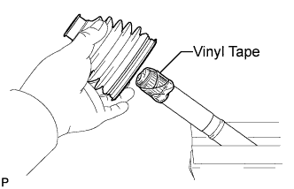
INSTALL OUTBOARD JOINT BOOT
Tech Tips
Before installing the boot, wrap the splines of the drive shaft with vinyl tape to prevent the boot from being damaged.
-
Install new parts to the outboard joint shaft in the following order:
-
Rear drive shaft outboard joint boot clamp
-
Outboard joint boot
-
No. 2 rear drive shaft outboard joint boot clamp
-
-
Pack the outboard joint shaft assembly and outboard joint boot with grease from the boot kit.
Grease capacity 95 to 105 g (3.4 to 3.7 oz.)
-
-
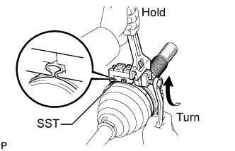
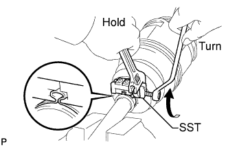
INSTALL REAR DRIVE SHAFT OUTBOARD JOINT BOOT CLAMP
-
Hold the rear drive shaft in a vise with aluminum plates in between.
-
Secure the rear drive shaft outboard joint boot clamp onto the boot.
-
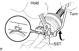
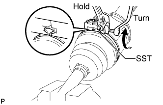
Place SST onto the rear drive shaft outboard joint boot clamp.
- SST
- 09521-24010
-
Tighten SST so that the rear drive shaft outboard joint boot clamp is pinched.
Note
Do not overtighten SST.
-
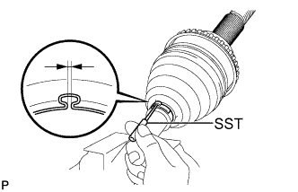
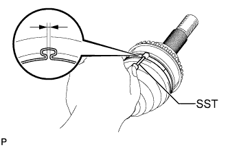
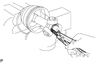
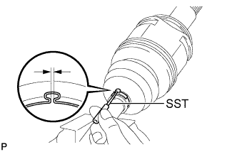
Using SST, inspect the clearance of the rear drive shaft outboard joint boot clamp.
- SST
- 09240-00020
Clearance 0.5 to 1.5 mm (0.0197 to 0.0591 in.) Note
If the measured value exceeds the specified value, retighten the clamp.
-
-
INSTALL NO. 2 REAR DRIVE SHAFT OUTBOARD JOINT BOOT CLAMP
-
Hold the front drive shaft in a vise between aluminum plates.
-
Secure the outboard joint boot clamp onto the boot.
-
Place SST onto the No. 2 rear drive shaft outboard joint boot clamp.
- SST
- 09521-24010
-
Tighten SST so that the No. 2 rear drive shaft outboard joint boot clamp is pinched.
Note
Do not overtighten SST.
-
Using SST, inspect the clearance of the No. 2 rear drive shaft outboard joint boot clamp.
- SST
- 09240-00020
Clearance 0.5 to 1.5 mm (0.0197 to 0.0591 in.) Note
If the measured value exceeds the specified value, retighten the clamp.
-
-
INSTALL REAR DRIVE SHAFT INBOARD JOINT ASSEMBLY
-
Wrap the splines of the outboard joint shaft with vinyl tape to prevent the boot from being damaged.
-
Install new parts to the outboard joint shaft in the following order:
-
No. 2 rear drive shaft inboard joint boot clamp
-
Inboard joint boot
-
Rear drive shaft inboard joint boot clamp
-
-
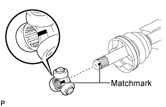
Place the beveled side of the tripod joint axial spline toward the outboard joint shaft assembly.
-
Align the matchmarks placed before removal.
-
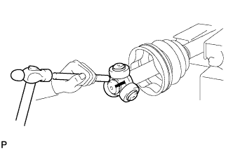
Using a brass bar and hammer, tap in the tripod joint onto the outboard joint shaft assembly.
Note
-
Do not tap the rollers.
-
Be sure to install the tripod joint in the correct direction.
-
-
Using a snap ring expander, install a new shaft snap ring.
-
Pack the outboard joint shaft and boot with grease.
Grease capacity 125.5 to 135.5 g (4.4 to 4.7 oz.) -
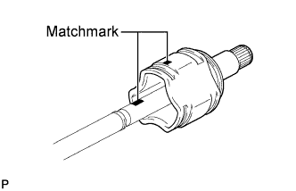
Align the matchmarks, and install the inboard joint assembly to the outboard joint shaft assembly.
-
-
INSTALL INBOARD JOINT BOOT
-
Install the inboard joint boot to the outboard joint shaft.
-
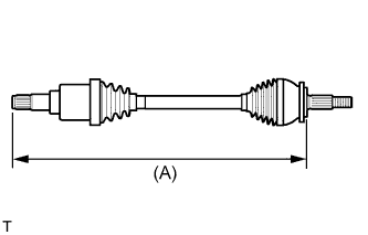
Check whether the drive shaft dimensions are within the following specifications.
Tech Tips
The following table shows dimension (A) of the drive shaft.
Dimension (A) 754.7 to 764.6 mm (29.71 to 30.10 in.)
-
-
INSPECT REAR DRIVE SHAFT INBOARD JOINT BOOT CLAMP
-
Hold the rear drive shaft in a vise with aluminum plates in between.
-
Secure the rear drive shaft inboard joint boot clamp onto the boot.
-
Place SST onto the rear drive shaft inboard joint boot clamp.
- SST
- 09521-24010
-
Tighten SST so that the rear drive shaft inboard joint boot clamp is pinched.
Note
Do not overtighten SST.
-
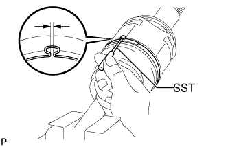
Using SST, inspect the clearance of the rear drive shaft inboard joint boot clamp.
- SST
- 09240-00020
Clearance 0.5 to 1.5 mm (0.0197 to 0.0591 in.) Note
If the measured value exceeds the specified value, retighten the clamp.
-
-
INSTALL NO. 2 REAR DRIVE SHAFT INBOARD JOINT BOOT CLAMP
-
Hold the rear drive shaft in a vise with aluminum plates in between.
-
Secure the No. 2 rear drive shaft inboard joint boot clamp onto the boot.
-
Place SST onto the No. 2 rear drive shaft inboard joint boot clamp.
- SST
- 09521-24010
-
Tighten SST so that the rear drive shaft inboard joint boot clamp is pinched.
Note
Do not overtighten SST.
-
Using SST, inspect the clearance of the inboard joint boot clamp.
- SST
- 09240-00020
Clearance 0.5 to 1.5 mm (0.0197 to 0.0591 in.) Note
If the measured value exceeds the specified value, retighten the clamp.
-
-
INSTALL REAR DRIVE SHAFT SNAP RING
-
Install a new rear drive shaft snap ring.
-
-
INSPECT REAR DRIVE SHAFT ASSEMBLY
-
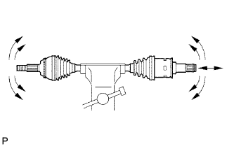
Check that there is no remarkable play in the radial direction of the outboard joint.
-
Check that the inboard joint slides smoothly in the thrust direction.
-
Check that there is no remarkable play in the radial direction of the inboard joint.
-
Check the boots for damage.
-