-
Use the same procedures for the RH side and LH side.
-
The procedures listed below are for the LH side.
- Click here
REMOVE ENGINE UNDER COVER ASSEMBLY
-

Remove the 2 bolts and engine under cover assembly RR.
-

Remove the 2 bolts, 2 screws, 5 clips and engine under cover assembly.
-
- Click here
REMOVE NO. 1 ENGINE UNDER COVER
-
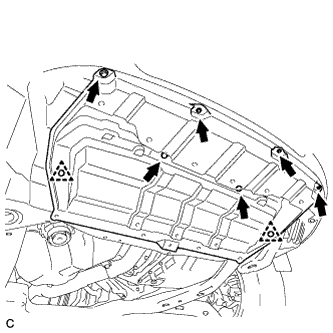
Remove the 6 bolts, 2 clips and No. 1 engine under cover.
-
- Click here
REMOVE NO. 2 ENGINE UNDER COVER
-
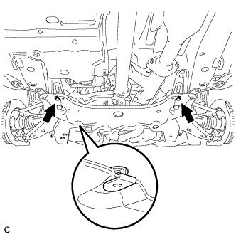
Remove the 2 bolts and No. 2 engine under cover.
-
- Click here
DRAIN AUTOMATIC TRANSAXLE FLUID
-
Remove the drain plug and gasket, and drain ATF.
-
Install a new gasket and the drain plug.
49 N*m 500 kgf*cm 36 ft.*lbf
-
- Click here
REMOVE NO. 1 TRANSFER CASE PLUG (for 4WD)
-
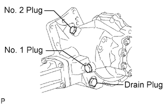
Remove the No. 1 transfer case plug.
-
Remove the No. 1 gasket from the No. 1 transfer case plug.
-
- Click here
REMOVE TRANSFER DRAIN PLUG (for 4WD)
-
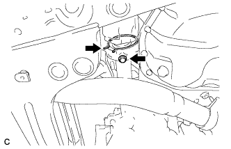
Remove the transfer drain plug and bleed the oil.
-
Remove the drain gasket from the transfer drain plug.
-
- Click here
REMOVE FRONT WHEELS
- Click here
REMOVE FRONT AXLE HUB NUT LH
-
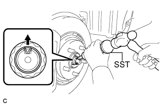
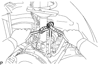
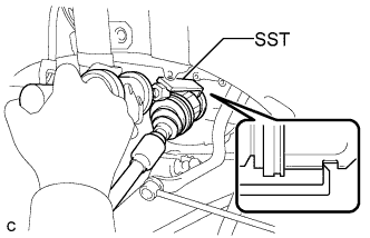
Using SST and a hammer, release the staked part of the front axle hub nut.
09930-00010 Note:Loosen the staked part of the nut completely, otherwise the threads of the drive shaft may be damaged.
-
While applying the brakes, remove the front axle hub nut.
-
- Click here
SEPARATE FRONT STABILIZER LINK ASSEMBLY LH
-
Remove the nut and separate the front stabilizer link assembly from the front shock absorber.
Tip:If the ball joint turns together with the nut, use a hexagon wrench (6 mm) to hold the stud.
-
- Click here
SEPARATE FRONT SPEED SENSOR LH
-
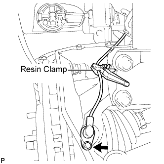
Remove the bolt and resin clamp, and separate the front speed sensor.
-
- Click here
SEPARATE TIE ROD ASSEMBLY LH
-
Remove the cotter pin and the nut.
-
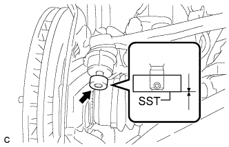
Install SST to the tie rod end.
09960-20010 09961-02060 Note:Make sure that the upper ends of the tie rod end and SST are aligned.
-
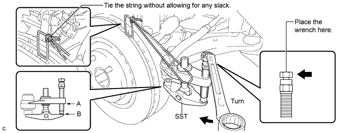
Using SST, separate the tie rod end from the steering knuckle.
09960-20010 09961-02010 Note:
-
When securing SST to the steering knuckle, be sure to tighten the string of SST to prevent it from falling.
-
Install SST so that A and B are parallel.
-
Be sure to place the wrench on the part indicated in the illustration.
-
Do not damage the front disc brake dust cover.
-
Do not damage the ball joint dust cover.
-
Do not damage the steering knuckle.
-
-
- Click here
SEPARATE NO. 1 FRONT SUSPENSION LOWER ARM LH
-
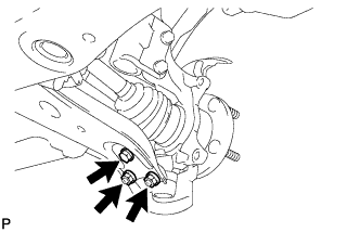
Remove the bolt and 2 nuts, and separate the front lower suspension arm from the front lower ball joint.
-
- Click here
SEPARATE FRONT AXLE ASSEMBLY LH
-
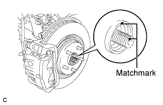
Put matchmarks on the front drive shaft assembly and the front axle hub sub-assembly.
Note:Do not punch the marks.
-
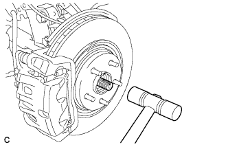
Using a plastic hammer, separate the front drive shaft assembly from the front axle assembly.
Note:Be careful not to damage the drive shaft boot and speed sensor rotor.
-
- Click here
REMOVE FRONT DRIVE SHAFT ASSEMBLY LH
-
Using SST, remove the front drive shaft assembly LH.
09520-01010 09520-24010 09520-32040 Note:
-
Be careful not to damage the drive shaft dust cover, boot, or oil seal.
-
Be careful not to drop the drive shaft assembly.
-
-
- Click here
REMOVE FRONT DRIVE SHAFT ASSEMBLY RH (for 2WD)
-
Remove the bearing bracket hole snap ring from the drive shaft bearing bracket.
-
Remove the bolt and front drive shaft assembly RH from the drive shaft bearing bracket.
Note:Do not damage the boot or oil seal.
-
- Click here
REMOVE FRONT DRIVE SHAFT ASSEMBLY RH (for 4WD)
Tip:Perform the same procedure as for the LH side.
- Click here
SECURE FRONT AXLE HUB SUB-ASSEMBLY
-
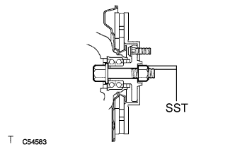
Using SST, secure the front axle hub bearing.
09608-16042 09608-02021 09608-02041 Note:The hub bearing may be damaged if it is subjected to the vehicle's full weight, such as when moving the vehicle with the drive shaft removed. If it is necessary to place the vehicle's weight on the hub bearing, first support it with SST.
-