- Click here
INSTALL TRANSFER EXTENSION HOUSING TYPE T OIL SEAL
-
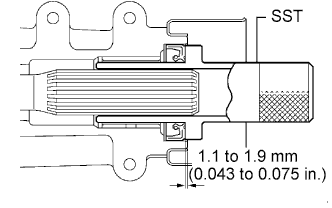
Using SST, install a new transfer extension housing type T oil seal to the transfer extension housing sub-assembly at the position shown in the illustration.
09325-20010 Note:
-
Do not install the oil seal obliquely.
-
Do not damage the oil seal lip.
-
-
Apply small amount of MP grease to the oil seal lip.
-
- Click here
TEMPORARILY TIGHTEN PROPELLER WITH CENTER BEARING SHAFT ASSEMBLY
-
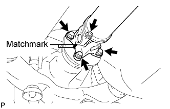
Align the matchmarks on the propeller shaft flange and differential companion flange, and connect the shaft with the 4 bolts, 4 washers and 4 nuts.
-
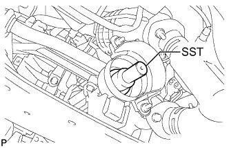
Remove SST from the transaxle.
-
Insert the yoke into the transaxle.
-
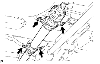
Install the 4 adjusting shims and propeller shaft with center bearing, and temporarily tighten the 4 bolts.
-
Tighten the 4 bolts.
74 N*m 750 kgf*cm 54 ft.*lbf
-
- Click here
FULLY TIGHTEN PROPELLER WITH CENTER BEARING SHAFT ASSEMBLY
-
Remove the piece of cloth from the joint.
-
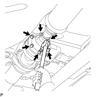
Using a hexagon wrench (6 mm), tighten the 6 bolts.
26 N*m 265 kgf*cm 19 ft.*lbf -
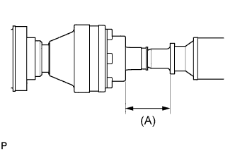
With the vehicle unloaded, adjust the dimension between the rear side of the cover and shaft as shown in the illustration.
(A) 58.0 +/- 0.5 mm (2.283 +/- 0.02 in.) -
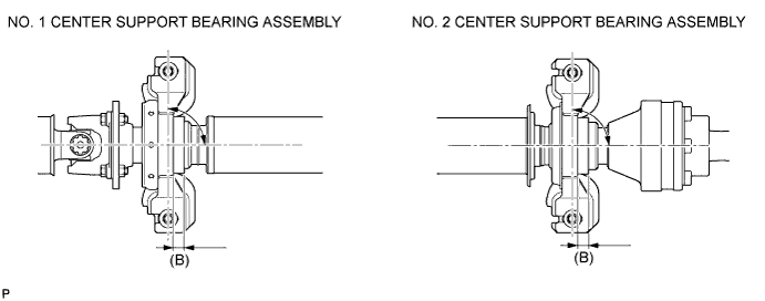
Under the same condition as above, adjust the front and rear dimensions between the edge surface of the center support bearing and the edge surface of the cushion respectively as shown, and then tighten the bolts.
37 N*m 375 kgf*cm 27 ft.*lbf (B) 12.5 +/- 1.0 mm (0.492 +/- 0.039 in.) -
Check that the center line of the bracket is at the right angle in the shaft axial direction.
-
If any vibration or noise occurs, perform joint angle check as follows and replace the adjusting shim with a proper one.
-
Turn the propeller shaft several times by hand to stabilize the center support bearings.
-
Using a jack, raise and lower the differential to stabilize the differential mounting cushion.
-
Remove the transfer dynamic damper.
-
Using SST, measure the transfer installation angle (A) and front propeller shaft installation angle (B).
09370-50010 No. 1 joint angle (A) - (B) = -1.3° to -3.3° -
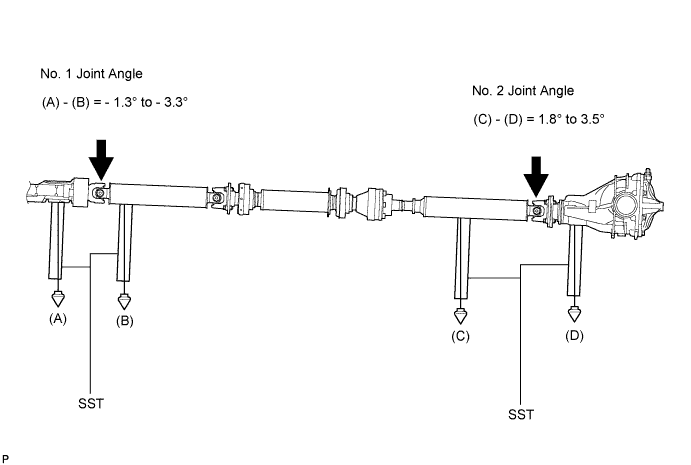
Using SST, measure the rear propeller shaft installation angle (C) and rear differential shaft installation angle (D).
09370-50010 No. 2 joint angle (C) - (D) = 1.8° to 3.5° Tip:If the measured angle is not within the specification, adjust it with the center support bearing adjusting shim.
Center support bearing adjusting shim thickness Thickness mm (in.) Thickness mm (in.) 3.2 (0.126) 11.0 (0.433) 4.5 (0.177) 13.5 (0.531) 6.5 (0.256) 15.5 (0.610) 9.0 (0.354) 17.5 (0.689) -
Install the transfer dynamic damper.
26 N*m 265 kgf*cm 19 ft.*lbf
-
-
- Click here
INSTALL TRANSFER DRAIN PLUG
-
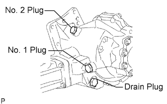
Install the transfer drain plug with a new drain gasket.
49 N*m 500 kgf*cm 36 ft.*lbf
-
- Click here
INSTALL NO. 1 TRANSFER CASE PLUG
-
Add oil up to 0 to 5 mm below the lower side of the plug hole.
Oil quantity 0.9 liters (0.95 US qts, 0.79 lmp.qts) Tip:When adding oil, pour it slowly.
-
Install the No. 1 transfer case plug with a new No. 1 gasket.
49 N*m 500 kgf*cm 36 ft.*lbf
-