- Click here
INSTALL TRANSFER RH BEARING RETAINER OIL SEAL
-
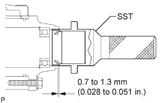
Using SST, install a new transfer RH bearing retainer oil seal to the transfer case at the position as show in the illustration.
09223-46011 Note:
-
Do not install the oil seal obliquely.
-
Do not damage the oil seal lip.
-
-
Apply small amount of MP grease to the oil seal lip.
-
- Click here
REMOVE FRONT DRIVE SHAFT HOLE SNAP RING
-
Install a new front drive shaft hole snap ring.
-
- Click here
INSTALL FRONT DRIVE SHAFT ASSEMBLY RH (for 2WD)
-
Install the front drive shaft assembly RH.
-
Install a new bearing bracket hole snap ring and bolt.
32 N*m 330 kgf*cm 24 ft.*lbf Note:
-
Do not damage the boot or oil seal.
-
Move the drive shaft assembly while keeping it level.
-
-
- Click here
INSTALL FRONT DRIVE SHAFT ASSEMBLY RH (for 4WD)
Tip:Perform the same procedure as for the LH side.
- Click here
INSTALL FRONT AXLE ASSEMBLY
-
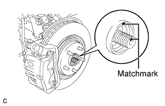
Align the matchmarks and install the front drive shaft assembly to the front axle hub sub-assembly.
-
- Click here
INSTALL NO. 1 FRONT SUSPENSION LOWER ARM
-
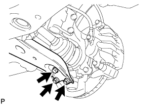
Install the No. 1 front suspension lower arm to the front lower ball joint with the bolt and 2 nuts.
92 N*m 938 kgf*cm 68 ft.*lbf
-
- Click here
INSTALL TIE ROD END SUB-ASSEMBLY
-
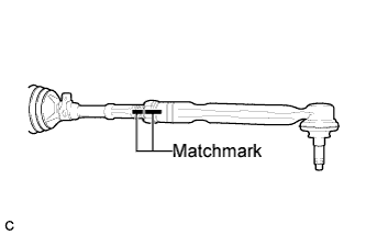
Install the lock nut and the tie rod assembly LH to the steering rack end sub-assembly until the matchmarks are aligned.
Tip:After adjusting toe-in, torque the lock nut.
-
- Click here
INSTALL FRRONT SPEED SENSOR
-
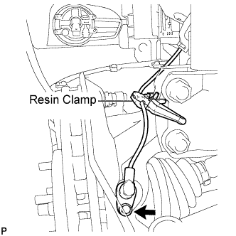
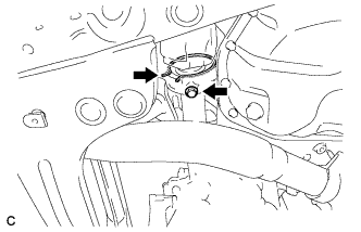
Install the resin clamp and front speed sensor with the bolt.
8.0 N*m 82 kgf*cm 71 in.*lbf Note:
-
Prevent foreign matter from attaching to the sensor tip.
-
Firmly insert the sensor body into the knuckle before tightening the bolt.
-
After installing the sensor to the knuckle, make sure that there is no clearance between the sensor stay and knuckle. Also make sure that no foreign matter is stuck between the parts.
-
To prevent interference between the sensor and magnetic rotor, do not rotate the sensor body during or after the insertion of the sensor body to the knuckle.
-
-
- Click here
INSTALL FRONT STABILIZER LINK ASSEMBLY
-
Install the front stabilizer link assembly to the front shock absorber with the nut.
74 N*m 755 kgf*cm 55 ft.*lbf Note:If the ball joint turns together with the nut, use a hexagon wrench (6 mm) to hold the stud bolt.
-
- Click here
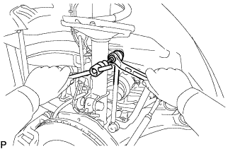
INSTALL FRONT AXLE HUB NUT
-
Clean the threaded parts on the drive shaft and axle hub nut using a non-residue solvent.
Tip:
-
Be sure to perform this work for a new drive shaft.
-
Keep the threaded parts free of oil and foreign objects.
-
-
Using a socket wrench (30 mm), install a new axle hub nut.
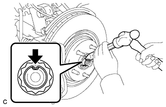
294 N*m 2996 kgf*cm 216 ft.*lbf -
Using a chisel and hammer, stake the front axle hub nut.
-
- Click here
INSTALL FRONT WHEEL
103 N*m 1050 kgf*cm 76 ft.*lbf - Click here
ADD AUTOMATIC TRANSAXLE FLUID
- Click here
INSPECT FLUID LEVEL
- Click here
INSTALL TRANSFER DRAIN PLUG
-
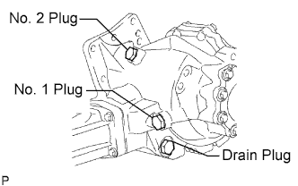
Install the transfer drain plug with a new drain gasket.
49 N*m 500 kgf*cm 36 ft.*lbf
-
- Click here
INSTALL NO. 1 TRANSFER CASE PLUG
-
Add oil up to 0 to 5 mm below the lower side of the plug hole.
Oil quantity 0.9 liters (0.95 US qts, 0.79 lmp.qts) Tip:When adding oil, pour it slowly.
-
Install the No. 1 transfer case plug with a new No. 1 gasket.
49 N*m 500 kgf*cm 36 ft.*lbf
-
- Click here
INSPECT EXHAUST GAS LEAK
- Click here
INSTALL NO. 2 ENGINE UNDER COVER
- Click here
INSTALL NO. 1ENGINE UNDER COVER
- Click here
INSTALL ENGINE UNDER COVER ASSEMBLY
- Click here
INSPECT AND ADJUST FRONT WHEEL ALIGNMENT
Tip: - Click here
CHECK ABS SPEED SENSOR SIGNAL
Tip: