DIFFERENTIAL CASE REASSEMBLY
-
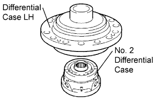
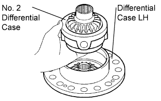
INSTALL NO. 2 DIFFERENTIAL CASE SUB-ASSEMBLY
-
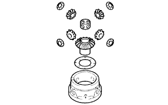
Coat the front differential side gear thrust washer, front differential gear, front differential pinion, front differential pinion thrust washer, front differential pinion shaft holder, and 3 differential pinion shafts with ATF, and install them to the No. 2 differential case.
-
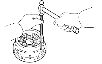
Using a pin punch and a hammer, install the 3 straight pins.
-
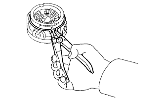
Using a snap ring expander, install the pinion shaft spacer snap ring.
-
-
INSPECT FRONT DIFFERENTIAL
-
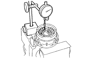
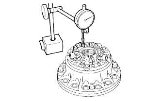
Using a dial indicator, measure the backlash of one pinion gear while holding the front differential side gear toward the case.
Standard backlash 0.05 to 0.20 mm (0.0020 to 0.0079 in.) Note
Do not mount the surface of the front differential case which contacts with the bushing in a vise.
If the backlash is not within the specified range, refer to the table below and select a thrust washer so that the backlash is within the specified range.
Thrust washer thickness: mm (in.) Mark Thickness Mark Thickness A 0.95 (0.0373) F 1.20 (0.0472) B 1.00 (0.0393) G 1.25 (0.0492) C 1.05 (0.0413) H 1.30 (0.0512) D 1.10 (0.0433) J 1.35 (0.0532) E 1.15 (0.0453) K 1.40 (0.0552) -
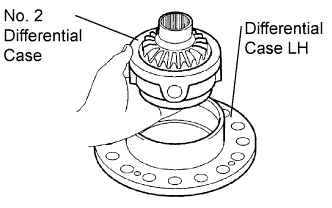
Engage the front differential side to the above mentioned front differential case.
-
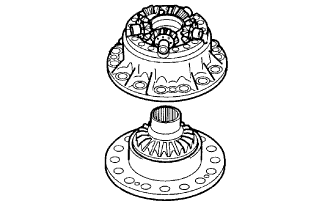
Install the differential case LH to the front differential case and measure its center.
-
After that, remove the differential case LH.
-
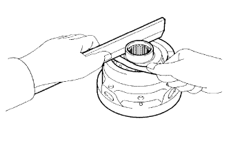
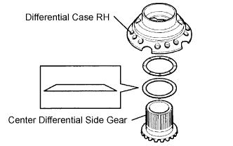
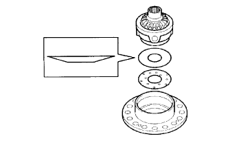
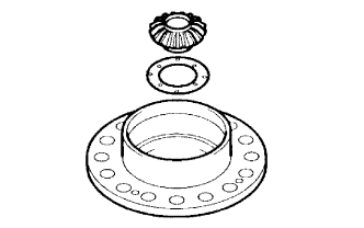
Using a straightedge and feeler gauge, measure the clearance between the front differential case and the front differential side gear.
Tech Tips
-
t= Thrust washer thickness
-
L= Clearance
-
t= L-0.162 to 0.265 mm (0.0064 to 0.0104 in.)
If the clearance is not within the specified range, refer to the table below and select a thrust washer so that the clearance is within the specified range.
Thrust washer thickness: mm (in.) Mark Thickness Mark Thickness A 0.95 (0.0373) F 1.20 (0.0472) B 1.00 (0.0393) G 1.25 (0.0492) C 1.05 (0.0413) H 1.30 (0.0512) D 1.10 (0.0433) J 1.35 (0.0532) E 1.15 (0.0453) K 1.40 (0.0552) If the clearance is not within the specified range, parts may have been assembled incorrectly, so check and reassemble it.
-
-
-
INSTALL CENTER DIFFERENTIAL PLANETARY GEAR ASSEMBLY
-
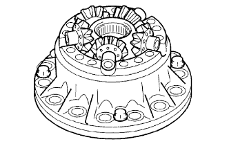
Install the center differential side gear, conical spring washer, and No. 2 center differential side gear thrust washer RH from the differential case RH.
Tech Tips
Ensure that the conical washers are installed correctly.
-
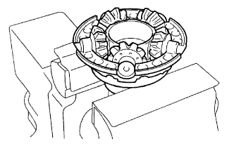
Hold the differential case RH in a vice. Install the center differential pinion and pinion thrust washer to the differential spider and install them to the differential case RH.
Note
When holding the differential case RH in a vise, be sure to place aluminum plates between them and use a minimum force.
-
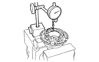
Pressing and holding the differential spider toward the differential case RH, measure the pinion's backlash with a dial indicator as illustrated.
Standard backlash 0.05 to 0.20 mm (0.0020 to 0.0079 in.) If the backlash is not within the specified range, refer to the table below and select a thrust washer so that the backlash is within the specified range.
Thrust washer thickness: mm (in.) Mark Thickness Mark Thickness MA 0.80 (0.0313) MH 1.15 (0.0453) MB 0.85 (0.0333) MJ 1.20 (0.0472) MC 0.90 (0.0353) MK 1.25 (0.0492) MD 0.95 (0.0373) ML 1.30 (0.0512) ME 1.00 (0.0393) MM 1.35 (0.0532) MF 1.05 (0.0413) MN 1.40 (0.0552) MG 1.10 (0.0433) - - -
Temporarily install the No. 2 differential side gear thrust washer LH, center differential side gear conical spring washer, and No. 2 differential case to the differential case LH.
Tech Tips
Ensure that the conical washers are installed correctly.
-
Install the differential intermediate case to the differential case and secure the assembled parts with the 4 bolts.
-
Remove the differential spider, 5 center differential pinions, and 5 center differential pinion thrust washers from the differential case RH. Put them in the differential intermediate case and secure the case.
-
Pressing and holding the differential spider toward the differential intermediate case, measure the pinion's backlash with a dial indicator.
Standard backlash 0.05 to 0.20 mm (0.0020 to 0.0079 in.) If the backlash is not within the specified range, refer to the table below and select a thrust washer so that the backlash is within the specified range.
Thrust washer thickness: mm (in.) Mark Thickness Mark Thickness MA 0.80 (0.0313) MH 1.15 (0.0453) MB 0.85 (0.0333) MJ 1.20 (0.0472) MC 0.90 (0.0353) MK 1.25 (0.0492) MD 0.95 (0.0373) ML 1.30 (0.0512) ME 1.00 (0.0393) MM 1.35 (0.0532) MF 1.05 (0.0413) MN 1.40 (0.0552) MG 1.10 (0.0433) - - -
Remove the 4 bolts and disconnect the differential case LH from the differential intermediate case.
-
Remove the No. 2 differential case from the differential case LH.
-
Install the selected No. 2 differential side gear thrust washer LH and center differential planetary gear to the differential case LH.
-
Install the No. 2 differential case to the differential case LH again.
-
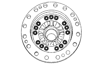
Install the adjusted differential case RH to the intermediate case and tighten the 15 bolts using a "TORX" socket wrench (T50).
- Torque:
- 63 N*m { 642 kgf*cm, 46 ft.*lbf }
Note
Align the matchmarks.
-
-
INSTALL FRONT DIFFERENTIAL CASE FRONT TAPERED ROLLER BEARING
-
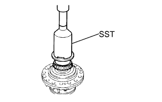
Using SST and a press, install the front differential case tapered roller bearing FR to the differential case.
- SST
- 09950-70010 ( 09951-07100 )
- 09649-17010
Note
Do not damage the bearing cage while installing the bearing inner race.
-
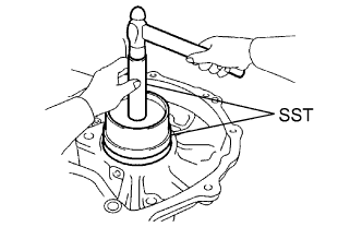
Using SST, install the outer race of the tapered roller bearing FR.
- SST
- 09527-17011
- 09950-60020 ( 09951-01030 )
Note
-
Clearance is not allowed between the plate washer and transaxle housing.
-
When replacing the bearing, be sure to replace both outer and inner races.
-
When replacing the bearing, be sure to replace both left and right bearings as a set.
-
-
INSTALL FRONT DIFFERENTIAL SIDE GEAR
-
Using SST and a press, install the front differential case tapered roller bearing RR to the differential case.
- SST
- 09316-20011
- 09214-76011
Note
Do not damage the bearing cage while installing the bearing inner race.
-
Install the front differential case shim RR to the transaxle case.
If the bearing is new, select a front differential case shim RR of proper thickness starting from the thinner ones. If the bearing is reused, select a front differential case shim RR starting from the same thickness as the one installed before disassembly.
-
Using SST, install the outer race of the front differential case tapered roller bearing RR.
- SST
- 09950-60020 ( 09951-00890 )
- 09950-70010 ( 09951-07100 )
Note
Clearance is not allowed between the differential case shim and transaxle case.
-
-
ADJUST TAPERED ROLLER BEARING PRELOAD
-

Install the intermediate case to the differential case LH and secure them with the 4 bolts.
-
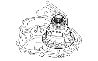
Install the differential assembly to the transaxle case.
-
Clean the matching surfaces of the transaxle case and transaxle housing.
-
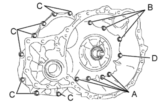
Install the transaxle housing to the transaxle case and tighten them with the 16 bolts.
- Torque:
- Bolt A
- 25 N*m { 255 kgf*cm, 18 ft.*lbf }
- Bolt B
- 33 N*m { 337 kgf*cm, 24 ft.*lbf }
- Bolt C
- 29 N*m { 295 kgf*cm, 21 ft.*lbf }
- Bolt D
- 28 N*m { 286 kgf*cm, 21 ft.*lbf }
Tech Tips
Apply adhesive or equivalent to bolts A and D
Adhesive Toyota Genuine Adhesive 1344, Three Bond 1344 or equivalent Bolt length Bolt A, B 50 mm (1.969 in.) Bolt C 42 mm (1.654 in.) Bolt D 72mm (2.835 in.) Note
Apply adhesive to the bolts and tighten them within 10 minutes of application
Tech Tips
Bolt A is a non-reusable bolt. However, bolt A can be used after cleaning it.
-
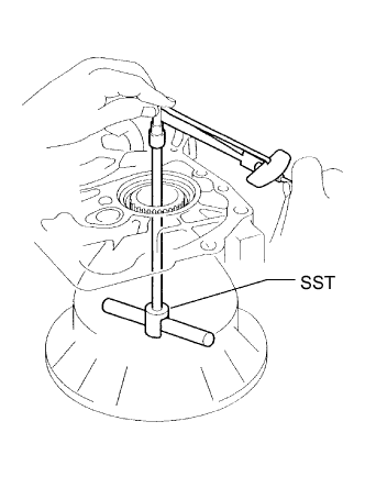
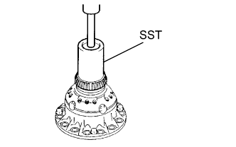
Using SST, turn the differential assembly right and left 2 or 3 times to allow the bearing to settle.
- SST
- 09564-32011
-
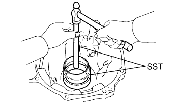
Using SST and a torque wrench, measure the turning torque of the differential case assembly.
- SST
- 09564-32011
- Torque:
- New bearing (*)
- 0.2 to 0.69 N*m { 2.0 to 7.0 kgf*cm, 1.8 to 6.1 in.*lbf }
- Used bearing (*)
- 0.10 to 0.35 N*m { 1.0 to 3.6 kgf*cm, 0.9 to 3.1 in.*lbf }
Tech Tips
-
(*): Turning torque at 60 rpm
-
If the turning torque is not within the specified range, refer to the table below and select a thrust washer so that the turning torque is within the specified range.
Flange thickness: mm (in.) Mark Thickness Mark Thickness 0 2.000 (0.0787) 9 2.450 (0.0965) j 2.025 (0.0797) T 2.475 (0.0974) 1 2.050 (0.0807) A 2.500 (0.0984) K 2.075 (0.0817) U 2.525 (0.0994) 2 2.100 (0.0827) B 2.550 (0.1004) L 2.125 (0.0837) V 2.575 (0.1014) 3 2.150 (0.0846) C 2.600 (0.1024) M 2.175 (0.0857) W 2.625 (0.1034) 4 2.200 (0.0866) D 2.650 (0.1043) N 2.225 (0.0876) X 2.675 (0.1053) 5 2.250 (0.0886) E 2.700 (0.1063) P 2.275 (0.0896) Y 2.725 (0.1073) 6 2.300 (0.0906) F 2.750 (0.1083) Q 2.325 (0.0915) AA 2.775 (0.1093) 7 2.350 (0.0925) G 2.800 (0.1102) R 2.375 (0.0935) AB 2.825 (0.1112) 8 2.400 (0.0945) H 2.850 (0.1122) S 2.425 (0.0954) - - -
Remove the 16 bolts and the transaxle housing.
-
Remove the differential assembly.
-
-
INSTALL FRONT DIFFERENTIAL RING GEAR
-
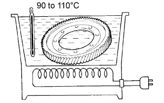
Using ATF and heater, heat the front differential ring gear to 90 to 110°C (194.0 to 230.0°F).
Note
Do not heat the ring gear to more than 110°C (230.0°F).
-
Clean the contact surface of the front differential case.
-
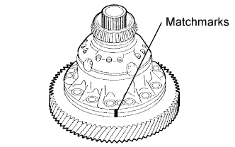
Align the matchmarks and install the front differential ring gear case quickly.
Note
-
Do not install the bolts while the ring gear is hot.
-
Check the number and position of the gear teeth.
-
-
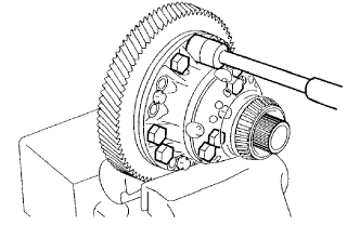
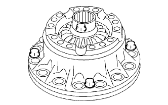
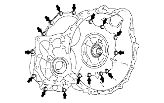
Temporarily install the 8 bolts as shown in the illustration.
-
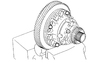
Remove the 4 bolts shown in the illustration.
-
Temporarily install the remaining 8 set bolts.
-
Fully tighten the set bolts.
- Torque:
- 95 N*m { 970 kgf*cm, 70 ft.*lbf }
Note
Tighten the bolts a little at a time in a diagonal pattern.
-
-
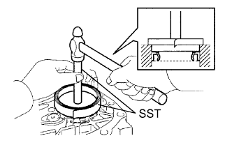
INSTALL DIFFERENTIAL SIDE BEARING RETAINER OIL SEAL
-
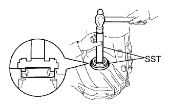
Using SST and a hammer, install a new oil seal.
- SST
- 09223-15020
- 09950-70010 ( 09951-07100 )
Standard installation depth -0.5 to 0.2 mm (-0.020 to 0.008 in.) -
Coat the lip of oil seal with a little MP grease.
-
-
INSTALL TRANSAXLE HOUSING OIL SEAL
-
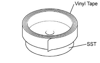
Wrap vinyl tape around SST at the place 6.0 mm (0.236 in.) above the bottom end until the thickness of the wrapped tape is approximately 5.0 mm (0.197 in.).
- SST
- 09950-60020 ( 09951-00730 )
Note
Remove foreign matter such as grease on the SST before winding the tape.
-
Coat the lip of oil seal with a little MP grease.
-
Using SST, install a new oil seal.
- SST
- 09950-60020 ( 09951-00730 )
- 09950-70010 ( 09951-07150 )
Standard installation depth 5.5 to 6.5 mm (0.217 to 0.256 in.) Note
Stop pressing when the wrapped vinyl tape contacts the transaxle housing.
-