TRANSFER ASSEMBLY REASSEMBLY
-
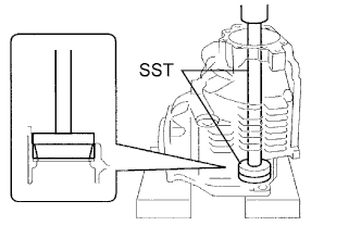
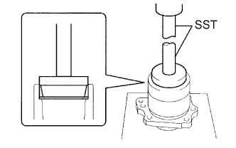
INSTALL TRANSFER DRIVEN PINION REAR BEARING
-
Using SST and a press, install the transfer driven pinion rear bearing outer race to the transfer case.
- SST
- 09950-60010 ( 09951-00620 )
- 09950-70010 ( 09951-07150 )
Note
Place something like wooden blocks under the case to keep its level.
-
-
INSTALL TRANSFER OUTPUT SHAFT WASHER
-
Install the transfer output shaft washer to the transfer case.
Tech Tips
Reuse the washer.
-
-
INSTALL TRANSFER DRIVEN PINION FRONT BEARING
-
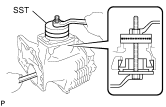
Install the transfer driven pinion front bearing outer race to the transfer case with SST, bolt and nut.
- SST
- 09316-60011 ( 09316-00061 )
- 09950-60020 ( 09951-00750, 09951-00770, 09951-00810 )
-
-
INSTALL RING GEAR MOUNTING CASE PLATE WASHER
-
Install the ring gear mounting case plate washer to the transfer case.
Tech Tips
Reuse the washer.
-
-
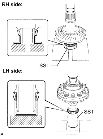
INSTALL CENTER DIFFERENTIAL CASE TAPERED ROLLER BEARING
-
Using SST and a press, install the center differential case tapered roller bearing LH outer race to the transfer case.
- SST
- 09950-60020 ( 09951-00680 )
- 09950-70010 ( 09951-07200 )
- SST
- 09950-70010 ( 09951-07200 )
-
-
INSTALL TRANSFER DRIVEN PINION FRONT BEARING
-
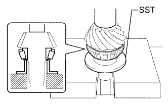
Using SST and a press, install the transfer driven pinion front bearing inner race to the driven pinion.
- SST
- 09316-60011 ( 09316-00041 )
-
-
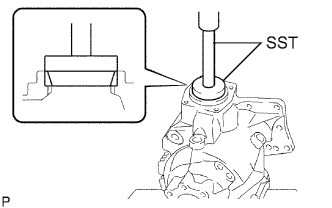
INSTALL DRIVEN PINION
-
Install the driven pinion to the transfer case.
-
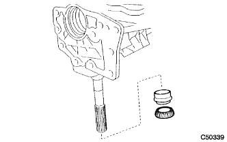
Install a new transfer pinion bearing spacer and a new transfer driven pinion rear bearing inner race to the driven pinion.
-
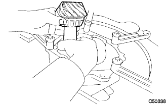
Using SST, tighten a new transfer gear nut (at a standard torque.).
- SST
- 09326-20011
- 09556-16030
- Torque:
- 277 to 378 N*m { 2820 to 3855 kgf*cm, 204 to 279 ft.*lbf }
Note
Do not stake the transfer gear nut.
Tech Tips
Use a torque wrench with a fulcrum length of 750 mm (29.53 in.).
-
-
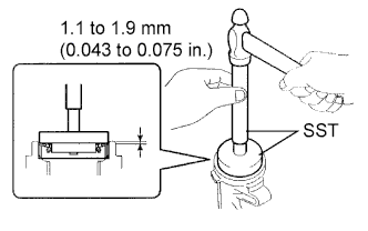
INSPECT AND ADJUST DRIVEN PINION PRELOAD
-
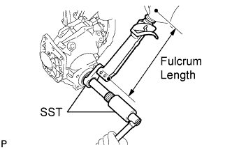
Using SST and a torque wrench, measure thee initial torque of the driven pinion.
- SST
- 09326-20011
- Torque:
- New bearing
- 1.1 to 1.6 N*m { 10 to 16 kgf*cm, 9.7 to 14.2 in.*lbf }
- Used bearing
- 0.9 to 1.4 N*m { 9 to 14 kgf*cm, 8.0 to 12.4 in.*lbf }
Tech Tips
Use a torque wrench with a fulcrum length of 160 mm (6.30 in.).
Note
Measure the preload after rotating the bearing both clockwise and counterclockwise to make it fit.
-
If the preload is too large, replace the transfer pinion bearing spacer with a new one.
-
If the preload is too small, repeatedly adjust the preload by tightening the transfer gear nut 5 to 10 degrees at a time until the standard value is obtained.
-
If the preload is insufficient, even though the tightening torque of the transfer gear nut exceeds the maximum of the standard value, loosen the transfer gear nut and apply gear oil SAE 90 (GL-5) to the transfer gear nut and the screw thread and the base of the driven pinion. And then repeat the preceding operation. If the tightening torque is bearing spacer with a new one and adjust it.
- Torque:
- 378 N*m { 3855 kgf*cm, 279 ft.*lbf }
-
-
INSTALL RING GEAR
-
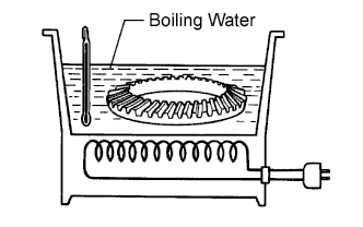
Heat the ring gear in boiling water from 90 to 100°C (194 to 212°F).
-
Completely remove grease and moisture on the contact surfaces of the ring gear and the transfer ring gear mounting case.
-
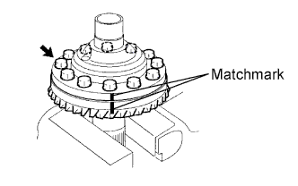
Align the matchmarks on the ring gear and transfer ring gear mounting case and quickly assemble them.
-
Tighten the 12 bolts.
- Torque:
- 78 N*m { 790 kgf*cm, 57 ft.*lbf }
Note
-
Tighten the bolts in diagonal order in splitting several times.
-
After the ring gear has well cooled down, fully tighten the bolts.
-
Make the bolt heads in order to check if they are retightened or not.
-
-
INSTALL CENTER DIFFERENTIAL CASE TAPERED ROLLER BEARING
-
Using SST and a press, install the inner race of the center differential case tapered roller bearing to the transfer ring gear mounting case.
- SST
- 09506-35010
- 09950-60010 ( 09951-00430 )
- 09223-00010
Note
When replacing the inner race, replace it together with the outer race.
-
-
INSTALL TRANSFER RING GEAR MOUNTING CASE
-
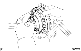
Install the transfer ring gear mounting case to the transfer case.
Note
Damage to the spline, the bearing's rotating surface and gear face may cause a decrease in their strength. Care should be taken when installing them.
-
-
INSTALL NO. 2 TRANSFER RING GEAR MOUNTING CASE WASHER
-
Install the No. 2 transfer ring gear mounting case washer to the transfer RH bearing retainer sub-assembly.
Tech Tips
Reuse the washer.
-
-
INSTALL CENTER DIFFERENTIAL CASE TAPERED ROLLER BEARING
-
Using SST and a press, install the center differential case tapered roller bearing RH outer race to the transfer RH bearing retainer sub - assembly.
- SST
- 09950-60010 ( 09951-00620 )
- 09950-70010 ( 09951-07150 )
-
-
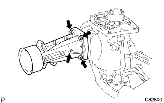
INSTALL TRANSFER RH BEARING RETAINER SUB-ASSEMBLY
-
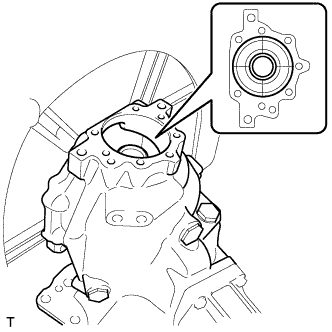
Place the transfer with the surface where the transfer RH bearing retainer sub-assembly is facing up.
-
Align the centers of the transfer ring gear mounting case and the transfer case.
-
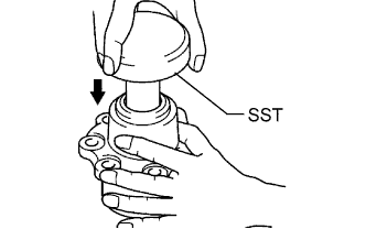
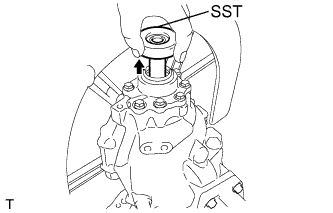
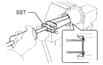
Insert SST into the transfer RH bearing retainer sub-assembly.
- SST
- 09387-00090
-
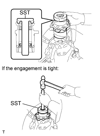
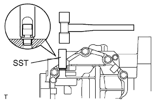
With SST and the transfer RH bearing sub-assembly in close contact, install the transfer RH bearing retainer sub-assembly together with SST into the transfer case.
Note
Avoid interference between the case and the retainer, and between SST and the transfer ring gear mounting case.
Tech Tips
If the engagement is tight, tap SST with a hammer placing a brass bar on the center of SST.
-
Make sure that the transfer RH bearing retainer sub-assembly and transfer case contact closely.
-
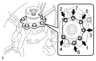
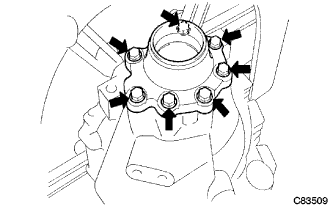
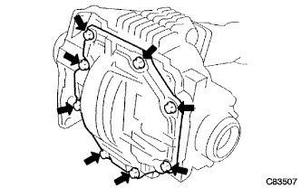
Tighten the 7 bolts evenly in order shown in the illustration.
- Torque:
- 28 N*m { 286 kgf*cm, 21 ft.*lbf }
-
Remove SST.
-
-
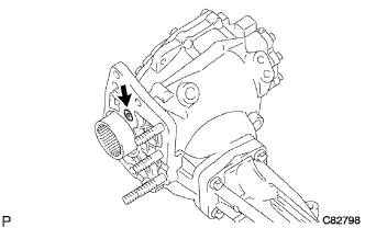
INSPECT DIFFERENTIAL RING GEAR BACKLASH
-
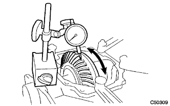
Set the dial gauge perpendicular to the ring gear face, fix the driven pinion, and check backlash by moving the ring gear.
Backlash 0.08 to 0.15 mm (0.0031 to 0.0059 in.) Note
Measure it at 3 points or more on the ring gear periphery.
-
If the measured value is out of standard, select a proper washer for the center differential case tapered roller bearing on the LH side from the table below and install it to obtain the standard value.
Mark Washer Thickness
mm (in.)
Mark Washer Thickness
mm (in.)
Mark Washer Thickness
mm (in.)
AA 2.07 (0.0814) AB 2.10 (0.0826) AC 2.13 (0.0838) BA 2.16 (0.0850) BB 2.19 (0.0862) BC 2.22 (0.0874) CA 2.25 (0.0885) CB 2.28 (0.0897) CC 2.31 (0.0909) DA 2.34 (0.0921) DB 2.37 (0.0933) DC 2.40 (0.0944) EA 2.43 (0.0956) EB 2.46 (0.0968) EC 2.49 (0.0980) FA 2.52 (0.0992) FB 2.55 (0.1003) FC 2.58 (0.1015) GA 2.61 (0.1027) GB 2.64 (0.1039) GC 2.67 (0.1051) HA 2.70 (0.1062) HB 2.73 (0.1074) HC 2.76 (0.1086) JA 2.79 (0.1098) JB 2.82 (0.1110) JC 2.85 (0.1122) KA 2.88 (0.1133) KB 2.91 (0.1145) KC 2.94 (0.1157) LA 2.97 (0.1169) LB 3.00 (0.1181) - - Tech Tips
When the backlash is larger or smaller than the standard, select a thinner or thicker washer respectively.
-
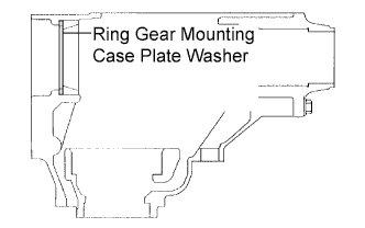
Ring gear mounting case plate washer location is shown in the illustration.
-
-
INSPECT TOOTH CONTACT BETWEEN RING GEAR AND DRIVE PINION
-
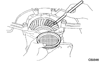
Apply Prussian blue thinly and uniformly to both faces of the ring gear and rotate it several times.
Note
Check the tooth contact on the ring gear at 4 places or more.
-
Observe the pattern shown by prussian blue.
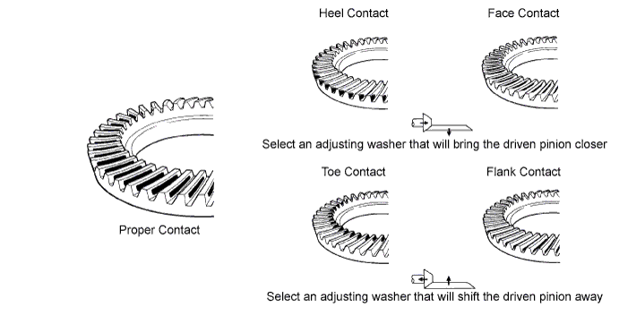
-
In case of poor tooth contact, select a washer for the driven pinion bearing front side from the following table and replace it.
Note
If the washer thickness is changed, the backlash will be also changed.
Mark Washer Thickness
mm (in.)
Mark Washer Thickness
mm (in.)
Mark Washer Thickness
mm (in.)
AA 1.20 (0.0472) AC 1.22 (0.0480) BB 1.24 (0.0488) CA 1.26 (0.0496) CC 1.28 (0.0503) DB 1.30 (0.0511) EA 1.32 (0.0519) EC 1.34 (0.0527) FB 1.36 (0.0535) GA 1.38 (0.0543) GC 1.40 (0.0551) HB 1.42 (0.0559) JA 1.44 (0.0566) JC 1.46 (0.0574) KB 1.48 (0.0582) LA 1.50 (0.0590) LC 1.52 (0.0598) MB 1.54 (0.0606) NA 1.56 (0.0614) NC 1.58 (0.0622) PB 1.60 (0.0629) QA 1.62 (0.0637) QC 1.64 (0.0645) - - -
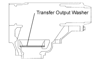
The location of the transfer output washer for tooth contact adjustment is shown in the illustration.
-
-
ADJUST TOTAL PRELOAD
-
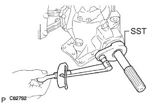
Using SST and a torque wrench, measure the initial torque with the driven pinion bearing contact with the ring gear face.
- SST
- 09326-20011
- Torque:
- New bearing
- 1.30 to 1.98 N*m { 13.3 to 20.2 kgf*cm, 11.5 to 17.5 in.*lbf }
- Used bearing
- 1.07 to 1.68 N*m { 10.9 to 17.1 kgf*cm, 9.5 to 14.9 in.*lbf }
Note
Before measurement, rotate the bearing in both directions several times to make it fit.
Tech Tips
Use a torque wrench with a fulcrum length of 160 mm (6.30 in.).
-
If the value is out of standard range, select the washer for the center differential case tapered roller bearing RH side from the following table and replace it.
Mark Washer Thickness mm (in.) Mark Washer Thickness mm (in.) Mark Washer Thickness mm (in.) AA 1.47 (0.0578) AB 1.50 (0.0590) AC 1.53 (0.0602) BA 1.56 (0.0614) BB 1.59 (0.0625) BC 1.62 (0.0637) CA 1.65 (0.0649) CB 1.68 (0.0661) CC 1.71 (0.0673) DA 1.74 (0.0685) DB 1.77 (0.0696) DC 1.80 (0.0708) EA 1.83 (0.0720) EB 1.86 (0.0732) EC 1.89 (0.0744) FA 1.92 (0.0755) FB 1.95 (0.0767) FC 1.98 (0.0779) GA 2.01 (0.0790) GB 2.04 (0.0803) GC 2.07 (0.0814) HA 2.10 (0.0826) HB 2.13 (0.0838) HC 2.16 (0.0850) JA 2.19 (0.0862) JB 2.22 (0.0874) JC 2.25 (0.0885) KA 2.28 (0.0897) KB 2.31 (0.0909) KC 2.34 (0.0921) LA 2.37 (0.0933) LB 2.40 (0.0944) LC 2.43 (0.0956) MA 2.46 (0.0968) MB 2.49 (0.0980) MC 2.52 (0.0992) NA 2.55 (0.1003) NB 2.58 (0.1015) - - -
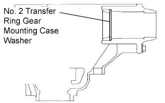
The location of the No. 2 transfer ring gear mounting case washer for preload adjustment is show in the illustration.
-
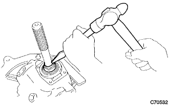
Using a chisel, stake the transfer gear nut.
-
-
REMOVE TRANSFER RH BEARING RETAINER SUB-ASSEMBLY
-
Remove the 7 bolts from the transfer RH bearing retainer sub-assembly.
-
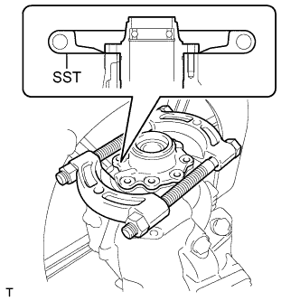
Using SST, make a clearance between the transfer RH bearing retainer sub-assembly and the transfer case.
- SST
- 09950-00020
-
Remove SST.
-
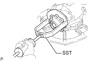
Using SST, remove the transfer RH bearing retainer sub - assembly from the transfer case.
- SST
- 09520-10021
-
-
REMOVE CENTER DIFFERENTIAL CASE TAPERED ROLLER BEARING
-
Fix the transfer RH bearing retainer sub-assembly in a vise.
-
Using SST, remove the center differential case tapered roller bearing RH outer race and transfer ring gear mounting case washer No. 2 from the transfer RH bearing retainer sub-assembly.
- SST
- 09308-00010
-
-
INSTALL SIDE GEAR SHAFT HOLDER BEARING
-
Install the side gear shaft holder bearing to the transfer RH bearing retainer sub-assembly.
-
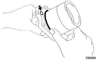
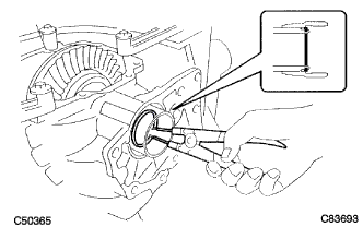
Using snap ring pliers, install the side gear shaft holder hole snap ring.
Tech Tips
Check that the side gear shaft holder hole snap ring fits in the groove of the transfer RH bearing retainer sub-assembly.
-
-
INSTALL TRANSFER RH BEARING RETAINER OIL SEAL
-
Using SST and a press, install the No. 2 transfer RH bearing retainer oil seal to the transfer RH bearing retainer sub-assembly.
- SST
- 09950-60010 ( 09951-00350, 09951-00540, 09952-06010 )
- 09950-70010 ( 09951-07150 )
Note
Carefully press-fit so that the oil seal will not be tilted.
-
Apply small amount of MP grease No. 2 to the oil seal lip.
-
-
INSTALL NO. 2 TRANSFER RING GEAR MOUNTING CASE WASHER
-
Install the No. 2 transfer ring gear mounting washer to the transfer RH bearing retainer sub-assembly.
-
-
INSTALL CENTER DIFFERENTIAL CASE TAPERED ROLLER BEARING
-
Using SST and a press, install the center differential case tapered roller bearing RH outer race to the transfer RH bearing retainer sub-assembly.
- SST
- 09950-60010 ( 09951-00620 )
- 09950-70010 ( 09951-07150 )
-
-
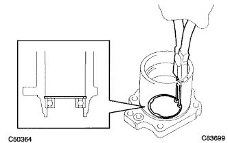
INSTALL O-RING
-
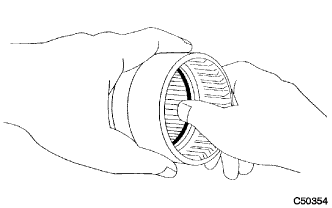
Coat 2 new O-rings with hypoid gear oil.
-
Install the 2 new O-rings to the transfer RH bearing retainer sub-assembly.
Note
Be careful not to twist the O-ring and fit it properly in the retainer's groove.
-
-
INSTALL TRANSFER RH BEARING RETAINER SUB-ASSEMBLY
-
Place the transfer with the surface where the transfer RH bearing retainer sub-assembly is facing up.
-
Align the centers of the transfer ring gear mounting case and the transfer case.
-
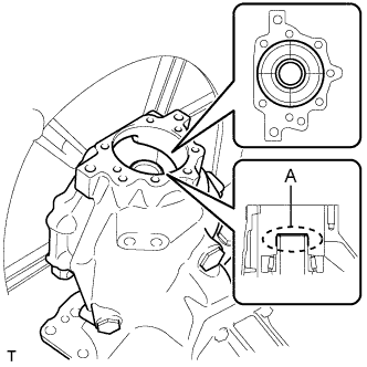
Apply MP grease No. 2 thinly to area A as shown in the illustration.
Tech Tips
Apply MP grease No. 2 to prevent the oil seal lip from rolling back.
-
Insert SST into the transfer RH bearing retainer sub-assembly.
- SST
- 09387-00090
Note
Insert SST straight in order not to damage the oil seal.
-
With SST and the transfer RH bearing sub-assembly in close contact, install the transfer RH bearing retainer sub-assembly together with SST into the transfer case.
Note
-
Avoid interference between the case and the retainer, and between SST and the transfer ring gear mounting case.
-
Carefully check the retainer's O-ring for damage and incorrect fitting.
Tech Tips
-
If the engagement is tight, tap SST with a hammer placing a brass bar on the center of SST.
-
If SST and retainer are not in close contact, the seal for the inner end of the retainer may not be properly aligned when the retainer goes into position. This may result in the lip of the oil seal being rolled back during installation.
-
If SST and retainer are not in close contact, the center of the retainer or transfer ring gear mounting case may come out of position when the retainer is being installed. This can cause the lip of the oil seal to be rolled back.
-
-
Make sure that the transfer RH bearing retainer sub-assembly and transfer case contact closely.
-
Tighten the 7 bolts evenly in order shown in the illustration.
- Torque:
- 28 N*m { 286 kgf*cm, 21 ft.*lbf }
-
Remove SST.
-
-
INSPECT TOTAL PRELOAD
-
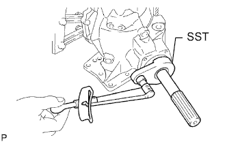
Using SST(s) and a torque wrench, measure the initial torque with the driven pinion being in contact with the ring gear face.
- SST
- 09326-20011
- Torque:
- New bearing
- 1.30 to 1.98 N*m { 13.3 to 20.2 kgf*cm, 11.5 to 17.5 in.*lbf }
- Used bearing
- 1.07 to 1.68 N*m { 10.9 to 17.1 kgf*cm, 9.5 to 14.9 in.*lbf }
Tech Tips
Use a torque wrench with a fulcrum length of 160 mm (6.30 in.).
-
-
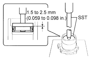
INSTALL TRANSFER RH BEARING RETAINER OIL SEAL
-
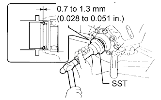
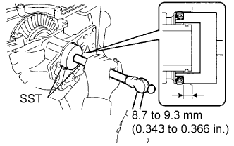
Using SST, install the transfer RH bearing retainer oil seal to the transfer RH bearing retainer sub-assembly to the position as shown in the illustration.
- SST
- 09223-46011
Note
-
Do not install the oil seal obliquely.
-
Do not damage the oil seal lip.
-
Apply MP grease to the oil seal lip.
-
-
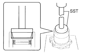
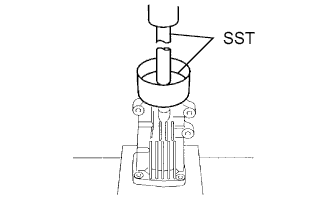
INSTALL TRANSFER CASE OIL SEAL
-
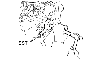
Using SST, install the transfer case oil seal to the transfer case at the position as shown in the illustration.
- SST
- 09387-00010
- 09950-70010 ( 09951-07150 )
Note
-
Do not install the oil seal obliquely.
-
Do not damage the oil seal lip.
-
Apply small amount of MP grease to the oil seal lip.
-
-
INSTALL CENTER DIFFERENTIAL LOCK SLEEVE
-
Coat a new O-ring with hypoid gear oil.
-
Install the O-ring to the CTR differential lock sleeve.
Note
Be careful not to twist the O-ring and fit it properly in the retainer's groove.
-
Using SST, install the CTR differential lock sleeve to the transfer case.
- SST
- 09950-60010 ( 09951-00610 )
- 09950-70010 ( 09951-07150 )
-
Using snap ring pliers, install the shaft snap ring.
Note
Check that the snap ring is fitted in the groove of the ring gear mounting case.
-
-
INSTALL TRANSFER EXTENSION HOUSING TYPE T OIL SEAL
-
Using SST, install the transfer extension housing type T oil seal to the transfer extension housing at the position as shown in the illustration.
- SST
- 09950-60010 ( 09951-00380, 09951-00580, 09951-07150, 09952-06010 )
- 09950-70010
Note
-
Do not install the oil seal obliquely.
-
Do not damage the oil seal lip.
-
Apply small amount of MP grease No. 2 to the oil seal lip.
-
-
INSTALL TRANSFER EXTENSION HOUSING DUST DEFLECTOR
-
Using SST and press, install a new transfer extension housing dust deflector to the transfer extension housing sub-assembly.
- SST
- 09950-60020 ( 09951-00710 )
- 09950-70010 ( 09951-07150 )
-
-
INSTALL TRANSFER EXTENSION HOUSING SUB-ASSEMBLY
-
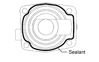
Apply sealant 1281 to the transfer extension housing sub-assembly in a continuous bead of 1.2 mm diameter as shown in the illustration.
Note
-
Wipe any grease off from the attaching surfaces.
-
Install the transfer extension housing sub-assembly within 10 minutes after applying the sealant.
-
-
Install the transfer extension housing sub-assembly to the transfer case with the 4 bolts.
- Torque:
- 26 N*m { 260 kgf*cm, 19 ft.*lbf }
-
Remove the transfer assembly from the overhaul attachment.
-
-
INSTALL TRANSFER AND TRANSAXLE SETTING STUD BOLT
-
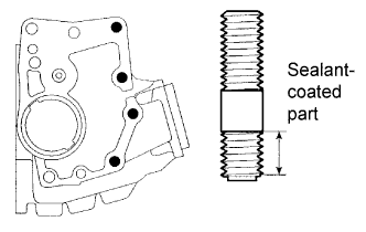
Install the transfer and transaxle setting stud bolts to the parts of the transfer case as shown in the illustration.
- Torque:
- 39 N*m { 400 kgf*cm, 30 ft.*lbf }
Note
Install the sealant-coated side of the transfer and transaxle stud bolt to the transfer case.
-
-
INSTALL TRANSFER CASE STRAIGHT PIN
-
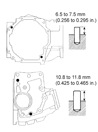
Using a plastic hammer, install the 4 transfer case straight pins to the transfer case as shown in the illustration.
-
-
INSTALL TRANSFER DYNAMIC DAMPER
-
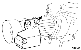
Install the transfer dynamic damper to the transfer extension housing sub-assembly with the 3 bolts.
- Torque:
- 26 N*m { 260 kgf*cm, 19 ft.*lbf }
-
-
INSTALL BREATHER OIL DEFLECTOR
-
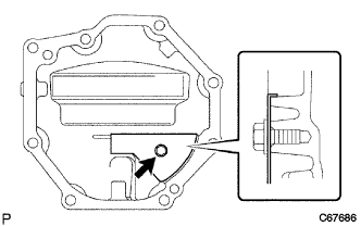
Install the breather oil deflector to the No. 1 transfer case cover with the bolt.
- Torque:
- 6.5 N*m { 66 kgf*cm, 57 in.*lbf }
Note
Be careful about the direction of the deflector's fold.
-
-
INSTALL NO. 1 TRANSFER CASE COVER
-
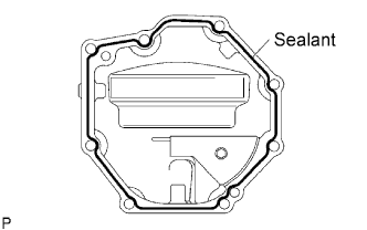
Apply sealant 1281 to the No. 1 transfer case cover in a continuous bead of 1.2 mm diameter as shown in the illustration.
Note
-
Wipe any grease off from the attaching surfaces.
-
Install the No. 1 transfer case cover within 10 minutes after applying the sealant.
-
-
Install the No. 1 transfer case cover to the transfer case with the 8 bolts.
- Torque:
- 20 N*m { 200 kgf*cm, 14 ft.*lbf }
-
-
INSTALL TRANSFER CASE BREATHER PLUG
-
Using SST and a hammer, install the transfer case breather plug to the No. 1 transfer case cover.
- SST
- 09612-10093 ( 09612-10061 )
-
-
INSTALL TRANSFER COVER GASKET
-
Install a new transfer cover gasket to the transfer case.
-