SHIFT LEVER INSPECTION
-
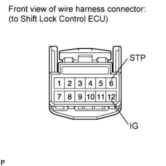
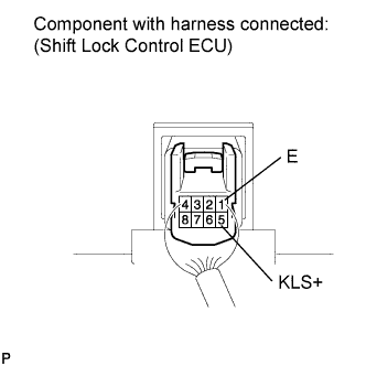
INSPECT SHIFT LOCK CONTROL ECU (w/ Smart Entry and Start System)
-
Disconnect the shift lock control ECU connector.
-
Measure the voltage according to the value(s) in the table below.
Standard voltage Tester Connection Condition Specified Condition 12 (IG) - Body ground Ignition switch on (IG) 10 to 14 V 12 (IG) - Body ground Ignition switch off Below 1 V 6 (STP) - Body ground Brake pedal depressed 10 to 14 V 6 (STP) - Body ground Brake pedal released Below 1 V -
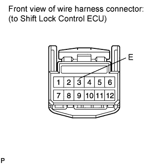
Measure the resistance according to the value(s) in the table below.
Standard resistance Tester Connection Condition Specified Condition 3 (E) - Body ground Always Below 1 Ω
-
-
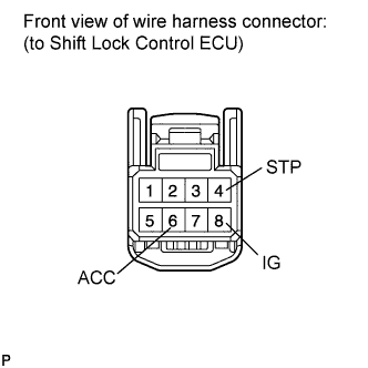
INSPECT SHIFT LOCK CONTROL ECU (w/o Smart Entry and Start System)
-
Disconnect the shift lock control ECU connector.
-
Measure the voltage according to the value(s) in the table below.
Standard voltage Tester Connection Condition Specified Condition 6 (ACC) - Body ground Ignition switch on (IG) 10 to 14 V 6 (ACC) - Body ground Ignition switch on (ACC) 10 to 14 V 6 (ACC) - Body ground Ignition switch off Below 1 V 4 (STP) - Body ground Brake pedal depressed 10 to 14 V 4 (STP) - Body ground Brake pedal released Below 1 V 8 (IG) - Body ground Ignition switch on (IG) 10 to 14 V 8 (IG) - Body ground Ignition switch off Below 1 V -
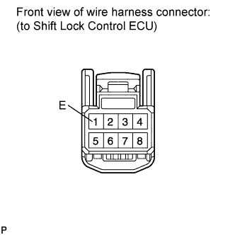
Measure the resistance according to the value(s) in the table below.
Standard resistance Tester Connection Condition Specified Condition 1 (E) - Body ground Always Below 1 Ω -
Connect the shift lock control ECU connector.
-
Measure the voltage according to the value(s) in the table below.
Note
Do not disconnect the shift lock control ECU connector.
Standard voltage Tester Connection Condition Specified Condition 5 (KLS+) - 1 (E) Ignition switch on (ACC) and shift lever P position Below 1 V Ignition switch on (ACC) and shift lever except P position
↓
After approx. 1 second
7.5 to 11 V
↓
6 to 9.5 V
-
-
INSPECT TRANSMISSION CONTROL SWITCH
-
Disconnect the transmission control switch connector from the shift lock control unit assembly.
-
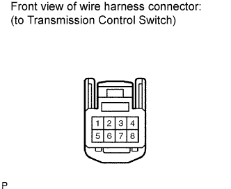
Measure the voltage according to the value(s) in the table below.
Standard voltage Tester Connection Switch Condition Specified Condition 3 - Body ground Ignition switch on (IG) 10 to 14 V ↑ Ignition switch off Below 1 V -
Measure the resistance according to the value(s) in the table below.
Standard resistance Tester Connection Condition Specified Condition 5 - Body ground Always Below 1 Ω -
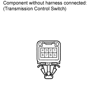
Measure the resistance according to the value(s) in the table below when the shift lever is moved to each position.
Standard resistance Tester Connection Shift Position Specified Condition 3 - 7 S, "+" and "-" Below 1 Ω ↑ Except S, "+" and "-" 10 kΩ or higher 2 - 5 Press continuously
"+"
(Up shift)
Below 1 Ω ↑ S 10 kΩ or higher 1 - 5 Press continuously
"-"
(Down shift)
Below 1 Ω ↑ S 10 kΩ or higher If the result is not as specified, replace the shift lock control unit.
-
-
INSPECT SHIFT LOCK SOLENOID
-
Disconnect the shift lock solenoid connector.
-
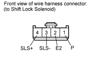
Measure the resistance according to the value(s) in the table below when the shift lever is moved to each position.
Standard resistance Tester Connection Shift Position Specified Condition 1 (P) - 2 (E2) P 10 kΩ or higher 1 (P) - 2 (E2) Except P Below 1 Ω If the result is not as specified, replace the shift lock control unit.
-
Measure the resistance according to the value(s) in the table below.
Standard resistance Tester Connection Condition Specified Condition 3 (SLS-) - 4 (SLS+) Always 112 Ω If the result is not as specified, replace the shift lock control unit.
-