- Click here
DISCONNECT CABLE FROM NEGATIVE BATTERY TERMINAL
CAUTION:Wait at least 90 seconds after disconnecting the cable from the negative (-) battery terminal to prevent airbag and seat belt pretensioner activation.
Note:When disconnecting the cable, some systems need to be initialized after the cable is reconnected (Click here).
- Click here
REMOVE CENTER INSTRUMENT CLUSTER FINISH PANEL ASSEMBLY (w/o Smart Entry and Start System)
-
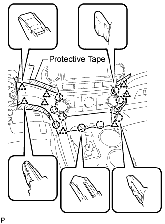
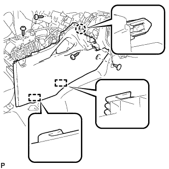
Apply protective tape to the areas shown in the illustration.
-
Using a moulding remover, disengage the 10 claws and 8 clips starting from the upper part of the center instrument cluster finish panel assembly.
Note:Do not pull on the small storage compartment lid. Doing so may cause damage.
-
Disconnect each connector and remove the center instrument cluster finish panel assembly.
-
- Click here
REMOVE CENTER INSTRUMENT CLUSTER FINISH PANEL ASSEMBLY (w/ Smart Entry and Start System)
-
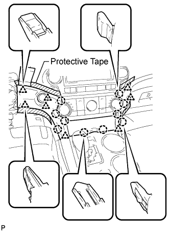
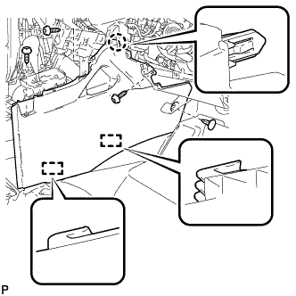
Apply protective tape to the areas shown in the illustration.
-
Using a moulding remover, disengage the 10 claws and 8 clips starting from the upper part of the center instrument cluster finish panel assembly.
Note:Do not pull on the small storage compartment lid. Doing so may cause damage.
-
Disconnect each connector and remove the center instrument cluster finish panel assembly.
-
- Click here
REMOVE FRONT DOOR SCUFF PLATE LH
-

Disengage the 8 claws and guide, and remove the front door scuff plate LH.
-
- Click here
REMOVE COWL SIDE TRIM SUB-ASSEMBLY LH
-

Remove the clip.
-
Disengage the clip and claw, and remove the cowl side trim sub-assembly LH.
-
- Click here
REMOVE LOWER INSTRUMENT PANEL FINISH PANEL SUB-ASSEMBLY (for Manual Air Conditioning System)
-

Remove the 2 bolts <B>.
-
Disengage the 3 claws and 10 clips.
-
Disconnect each connector.
-
Disconnect the hood lock control cable assembly and remove the lower instrument panel finish panel sub-assembly.
-
- Click here
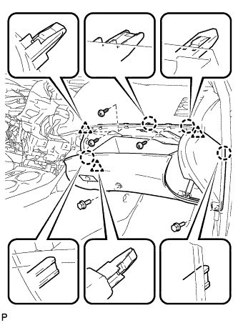
REMOVE LOWER INSTRUMENT PANEL FINISH PANEL SUB-ASSEMBLY (for Automatic Air Conditioning System)
-

Remove the 2 bolts <B>.
-
Disengage the 3 claws and 10 clips.
-

Disconnect each connector and the aspirator duct.
-
Disconnect the hood lock control cable assembly and remove the lower instrument panel finish panel sub-assembly.
-
- Click here
REMOVE FRONT DOOR SCUFF PLATE RH
Tip:Use the same procedure for the RH side and the LH side.
- Click here
REMOVE COWL SIDE TRIM SUB-ASSEMBLY RH
Tip:Use the same procedure for the RH side and the LH side.
- Click here
REMOVE NO. 2 INSTRUMENT PANEL UNDER COVER SUB-ASSEMBLY
-
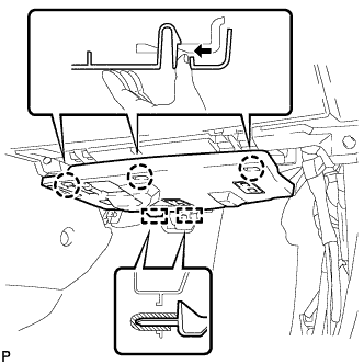
Disengage the 3 claws.
-
Disengage the 2 guides and remove the No. 2 instrument panel under cover sub-assembly.
-
- Click here
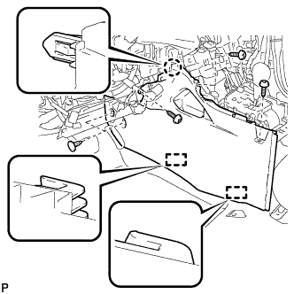
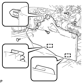
REMOVE LOWER INSTRUMENT PANEL SUB-ASSEMBLY
-
Remove the 2 bolts <B> and 3 screws <E>.
-
Disengage the 4 claws and 3 clips.
-
Disconnect each connector and clamp, and remove the lower instrument panel sub-assembly.
-
- Click here
REMOVE UPPER CONSOLE PANEL SUB-ASSEMBLY
-
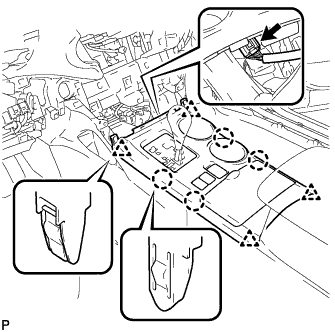
Disengage the 4 claws and 4 clips.
-
Disconnect the connector and remove the upper console panel sub-assembly.
-
- Click here
REMOVE NO. 2 CONSOLE BOX DUCT (w/o Rear Air Conditioning System)
-
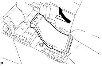
Remove the No. 2 console box duct as shown in the illustration.
-
- Click here
REMOVE LOWER REAR CONSOLE BOX
-
Remove the lower rear console box.
-
- Click here
REMOVE CONSOLE BOX ASSEMBLY (w/o Rear Air Conditioning System)
-
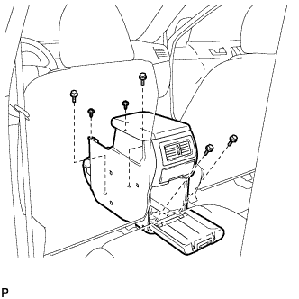
Remove the 4 bolts and 2 screws.
-
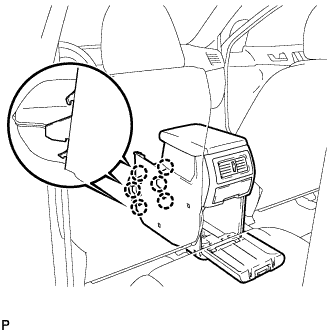
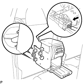
Disengage the 6 claws and remove the console box assembly.
-
- Click here
REMOVE CONSOLE BOX ASSEMBLY (w/ Rear Air Conditioning System)
-
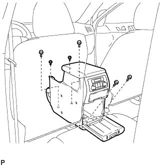
Remove the 4 bolts and 2 screws.
-
Disconnect the connector.
-
Disengage the 6 claws, and remove the console box assembly.
-
- Click here
REMOVE FRONT NO. 1 CONSOLE BOX INSERT (for LHD)
-
Using a clip remover, remove the 2 clips.
-
Remove the 3 screws <E>.
-
Disengage the claw and 2 guides, and then remove the front No. 1 console box insert.
-
- Click here
REMOVE FRONT NO. 1 CONSOLE BOX INSERT (for RHD)
-
Using a clip remover, remove the clip.
-
Remove the 3 screws <E>.
-
Disengage the claw and 2 guides, and then remove the front No. 1 console box insert.
-
- Click here
REMOVE FRONT NO. 2 CONSOLE BOX INSERT (for LHD)
-
Using a clip remover, remove the clip.
-
Remove the 3 screws <E>.
-
Disengage the claw and 2 guides, and then remove the front No. 2 console box insert.
-
- Click here
REMOVE FRONT NO. 2 CONSOLE BOX INSERT (for RHD)
-
Using a clip remover, remove the clip.
-
Remove the 3 screws <E>.
-
Disengage the claw and 2 guides, and then remove the front No. 2 console box insert.
-
- Click here
REMOVE SHIFT LEVER KNOB SUB-ASSEMBLY
-
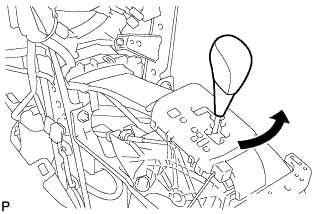
Turn the shift lever knob counterclockwise and remove the shift lever knob sub-assembly.
-
- Click here
DISCONNECT TRANSMISSION CONTROL CABLE ASSEMBLY
-
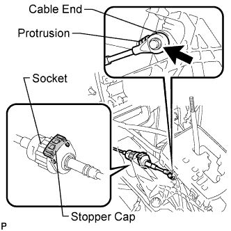
Using a screwdriver, disconnect the cable end from the shift lever assembly.
-
Turn the socket of the transmission control cable assembly counterclockwise and remove the stopper cap.
-
Disconnect the transmission control cable assembly from the shift lever assembly.
-
- Click here
REMOVE SHIFT LEVER ASSEMBLY
-
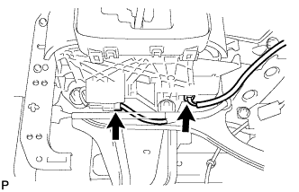
Disconnect the 2 connectors from the shift lever assembly.
-
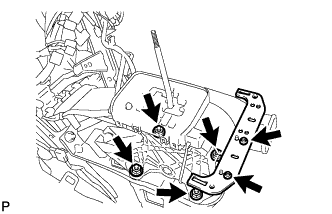
Remove the 4 nuts and disconnect the shift lever assembly from the vehicle.
-
Remove the 2 screws and No. 2 console box mounting bracket.
-