AUTOMATIC TRANSAXLE UNIT INSPECTION
-
INSPECT MULTIPLE DISC CLUTCH HUB
-
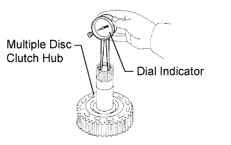
Using a dial indicator, measure the inside diameter of the forward clutch hub bushing.
Standard inside diameter 23.025 to 23.046 mm (0.9065 to 0.9073 in.) Maximum inside diameter 23.09 mm (0.9091 in.) Note
-
Check the contact surface of the bushing in the direct clutch shaft. If any scratch or discoloration is found, replace the direct clutch sub-assembly with a new one.
If the inside diameter is greater than the maximum, replace the forward clutch hub with a new one.
-
-
-
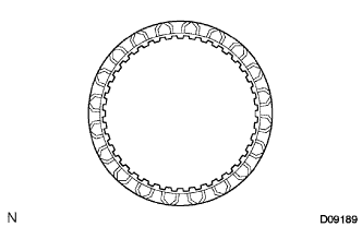
INSPECT NO. 2 UNDERDRIVE CLUTCH DISC
-
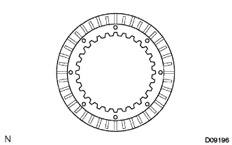
Check if the sliding surfaces of the disc, plate, and flange are worn or burnt.
If necessary, replace them.
Note
-
If the lining of the disc comes off or discolors, or if a part of the groove is worn, replace all discs.
-
Before installing new discs, immerse them in ATF for at least 15 minutes.
-
-
-
INSPECT OVERDRIVE DIRECT CLUTCH DRUM SUB-ASSEMBLY
-
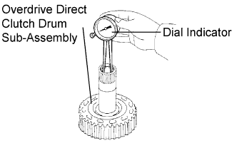
Using a dial indicator, measure the inside diameter of the forward clutch hub bushing.
Standard inside diameter 23.025 to 23.046 mm (0.9065 to 0.9073 in.) Maximum inside diameter 23.09 mm (0.9091 in.) Note
-
Check the contact surface of the bushing in the direct clutch shaft. If any scratch or discoloration is found, replace the direct clutch sub-assembly with a new one.
If the inside diameter is greater than the maximum, replace the forward clutch hub with a new one.
-
-
-
INSPECT 2ND BRAKE CLUTCH DISC
-
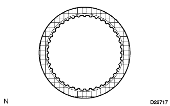
Check if the sliding surface of the disc, plate, and flange are worn or burnt.
If necessary, replace them.
Note
-
If the lining of the disc comes off or discolors, or if a part of the groove is worn, replace all discs.
-
Before installing new discs, immerse them in ATF for at least 15 minutes.
-
-
-
INSPECT 1ST AND REVERSE BRAKE CLUTCH DISC
-
Check if the sliding surface of the disc, plate, and flange are worn or burnt.
If necessary, replace them.
Note
-
If the lining of the disc comes off or discolors, or if a part of the groove is worn, replace all discs.
-
Before installing new discs, immerse them in ATF for at least 15 minutes.
-
-
-
INSPECT 1ST AND REVERSE BRAKE RETURN SPRING SUB-ASSEMBLY
-
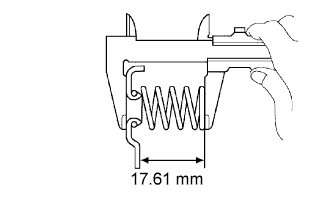
Using vernier calipers, measure the free length of the spring together with the spring seat.
Standard free length 17.61 mm (0.6933 in.) Tech Tips
If the result is not as specified, replace the spring.
-
-
INSPECT UNDERDRIVE BRAKE RETURN SPRING SUB-ASSEMBLY
-
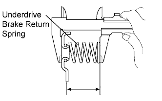
Using vernier calipers, measure the free length of the spring together with the spring seat.
Standard free length 13.24 mm (0.5213 in.) Tech Tips
If the result is not as specified, replace the spring.
-
-
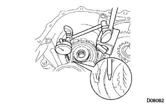
INSPECT PACK CLEARANCE OF 1ST AND REVERSE BRAKE
-
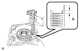
Using vernier calipers, measure the distance between the disc surface and the contact surface of the 2nd brake cylinder and transaxle case (Dimension A).
-
Select an appropriate flange so that the pack clearance will be within the specified range.
Pack clearance 1.16 to 1.35 mm (0.0457 to 0.0531 in.) Tech Tips
Piston stroke = Dimension A - Flange thickness
Flange thickness: mm (in.) Mark Thickness Mark Thickness 1 1.8 (0.071) 5 2.2 (0.087) 2 1.9 (0.075) 6 2.3 (0.091) 3 2.0 (0.079) 7 2.4 (0.094) 4 2.1 (0.083) 8 2.5 (0.098) -
Install the flange.
-
-
INSPECT PACK CLEARANCE OF 2ND BRAKE
-
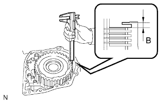
Using vernier calipers, measure the distance between the disc surface and snap ring surface (Dimension B).
-
Select an appropriate flange so that the pack clearance will be within the specified range.
Pack clearance 0.62 to 0.91 mm (0.0244 to 0.0358 in.) Tech Tips
Piston stroke = Dimension B - Flange thickness - Snap ring thickness 1.6 mm (0.063 in.)
Flange thickness: mm (in.) Mark Thickness Mark Thickness 1 3.0 (0.118) 5 3.4 (0.134) 2 3.1 (0.122) 6 3.5 (0.138) 3 3.2 (0.126) 7 3.6 (0.142) 4 3.3 (0.130) 8 -
-
-
INSPECT PACK CLEARANCE OF UNDERDRIVE BRAKE
-
Using a dial indicator, measure the underdrive brake pack clearance while applying and releasing compressed air (392 kPa, 4.0 kgf/cm2, 57 psi).
Pack clearance 1.81 to 2.20 mm (0.0713 to 0.0866 in.) Tech Tips
Select an appropriate flange from the table below so that it will be within the specified range.
Flange thickness: mm (in.) Mark Thickness Mark Thickness 1 3.0 (0.118) 4 3.1 (0.122) 2 3.2 (0.126) 5 3.3 (0.130) 3 3.4 (0.134) - - -
Temporarily remove the snap ring and attach it to the flange.
-
Reinstall the snap ring.
-
-
INSPECT UNDERDRIVE ONE-WAY CLUTCH ASSEMBLY
-
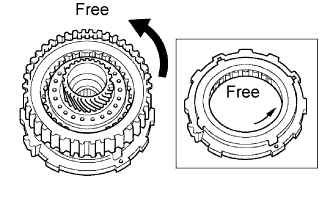
Install the underdrive clutch assembly to the one-way clutch.
-
Rotate the underdrive one-way clutch assembly to check the rotating direction for the lock or free operation.
Tech Tips
If the result is not as specified, replace the underdrive one-way clutch.
-
-
INSPECT INPUT SHAFT END PLAY
-
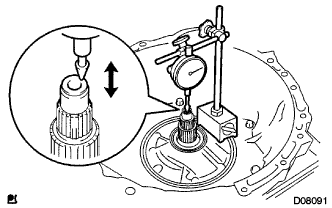
Using a dial indicator, measure the input shaft end play.
End play 0.262 to 1.244 mm (0.0103 to 0.0490 in.) Tech Tips
If the result is not as specified, replace the input shaft or thrust needle roller bearing.
-