AUTOMATIC TRANSAXLE ASSEMBLY INSTALLATION
-
INSTALL TORQUE CONVERTER CLUTCH ASSEMBLY
-
Install the torque converter clutch to the automatic transaxle.
-
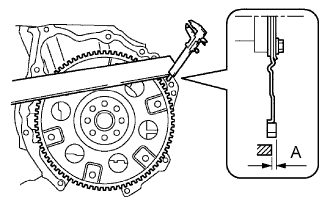
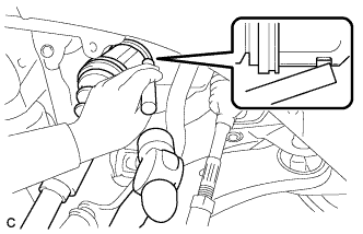
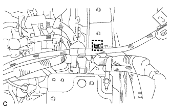
Using vernier calipers and a straight edge, measure dimension "A" between the transaxle fitting part of the engine and the converter fitting part of the drive plate (#).
-
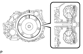
Aligning the matchmarks on the transaxle case and torque converter clutch assembly, engage the splines of the input shaft and turbine runner.
Note
Do not push on the torque converter when aligning the matchmarks.
-
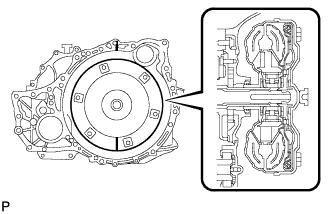
Engage the splines of the stator shaft and the stator while turning the torque converter clutch assembly.
Tech Tips
Turn the torque converter clutch assembly approximately 180°.
-
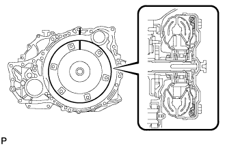
Turn the torque converter clutch assembly and align the matchmarks on the torque converter clutch assembly and transaxle case to engage the key of the oil pump drive gear into the slot on the torque converter clutch assembly.
-
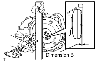
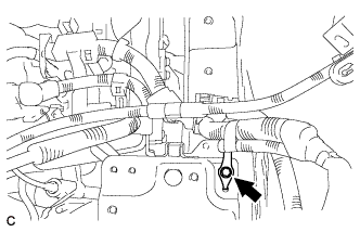
Using vernier calipers and a straight edge, measure dimension "B" shown in the illustration and check that "B" is greater than "A" (measured in step (#)).
Standard A + 1 mm (0.04 in.) or more Note
Make sure to deduct the thickness of the straight edge.
-
-
INSTALL TRANSFER ASSEMBLY
-
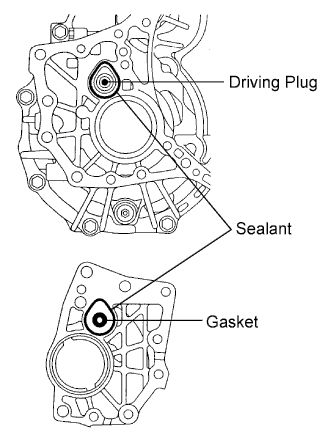
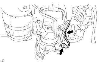
Apply sealant 1281 to the transaxle assembly and transfer assembly in a continuous bead of 1.2 mm diameter as shown in the illustration.
Note
-
Wipe any grease off from the attaching surfaces.
-
Install it within 10 minutes after applying the sealant.
-
Sealant stuck on the gasket, case oil seal and driving plug may cause oil leakage and seizure due to oil shortage. Care must be taken.
-
-
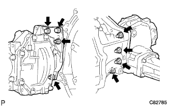
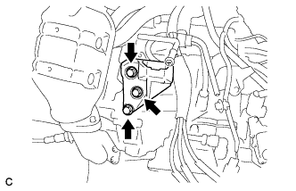
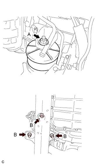
Install the transfer assembly to the transaxle assembly with the 2 bolts and 6 nuts.
- Torque:
- 69 N*m { 700 kgf*cm, 51 ft.*lbf }
Note
-
Check that the gasket is installed to the transfer assembly before installing them to the transaxle assembly.
-
Install the transfer assembly to the transaxle assembly without tilting.
-
When moving the transfer assembly, do not hold the oil seal on the both sides.
-
-
INSTALL AUTOMATIC TRANSAXLE WITH TRANSFER
-
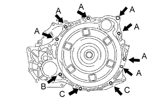
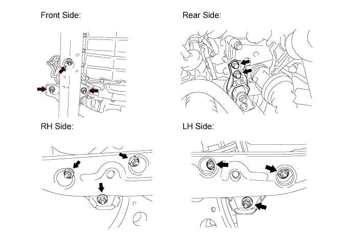
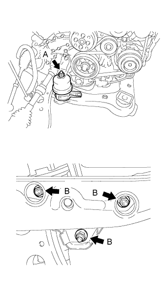
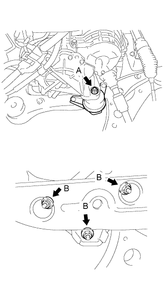
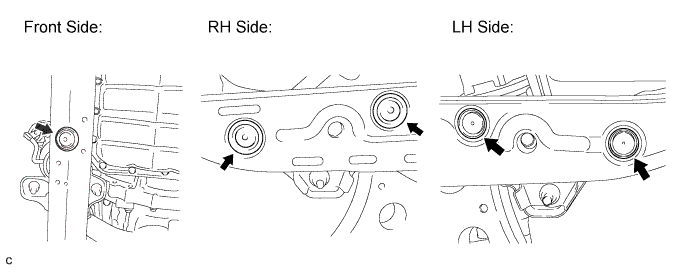
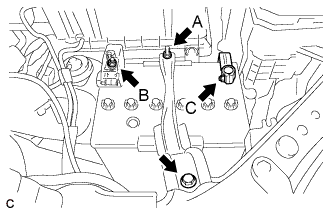
Install the automatic transaxle with transfer to the engine with the 10 bolts.
- Torque:
- Bolt A
- 64 N*m { 650 kgf*cm, 47 ft.*lbf }
- Bolt B
- 46 N*m { 470 kgf*cm, 34 ft.*lbf }
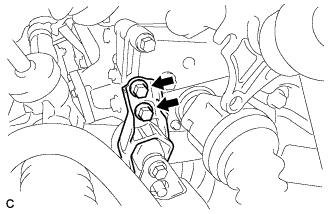
- Bolt C
- 43 N*m { 438 kgf*cm, 32 ft.*lbf }
-
Apply a few drops of adhesive to each of 2 threads on the tip of the 6 torque converter clutch mounting bolts.
Adhesive Toyota Genuine Adhesive 1324, Three Bond 1324 or equivalent -
Install the 6 torque converter clutch mounting bolts.
- Torque:
- 41 N*m { 418 kgf*cm, 30 ft.*lbf }
Note
First install the different colored bolt, and then the remaining 5 bolts.
-
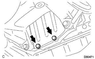
Install the flywheel housing under cover to the automatic transaxle with the 2 bolts.
- Torque:
- 7.8 N*m { 80 kgf*cm, 69 in.*lbf }
-
-
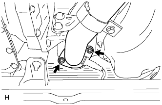
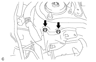
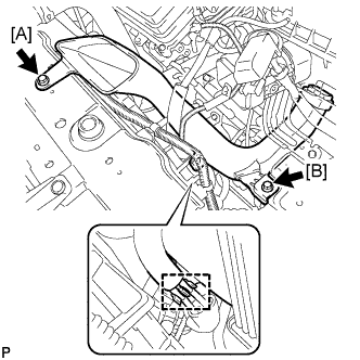
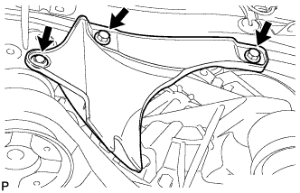
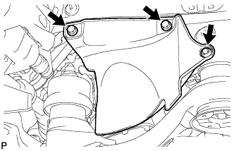
INSTALL TRANSFER STIFFENER PLATE RH
-
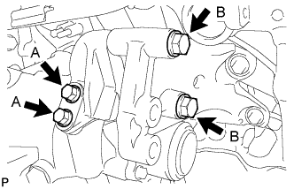
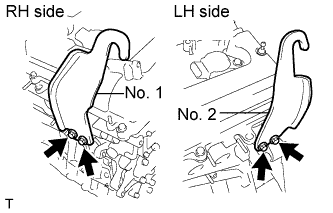
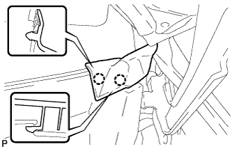
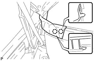
Install the transfer stiffener plate RH with 4 bolts to the transfer and engine mounting bracket RR.
- Torque:
- Bolt A
- 34 N*m { 350 kgf*cm, 25 ft.*lbf }
- Bolt B
- 78 N*m { 796 kgf*cm, 58 ft.*lbf }
-
-
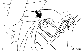
INSTALL TRANSMISSION OIL FILLER TUBE SUB-ASSEMBLY
-
Coat a new O-ring with ATF, and install it to the transmission oil filler tube sub-assembly.
-
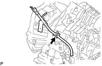
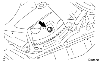
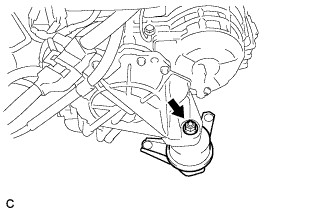
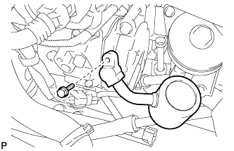
Install the transmission oil filler tube sub-assembly to the automatic transaxle with the bolt.
- Torque:
- 5.5 N*m { 56 kgf*cm, 49 in.*lbf }
-
-
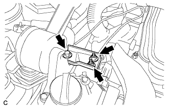
INSTALL NO. 1 OIL COOLER INLET TUBE
-
Temporarily install the No. 1 oil cooler outlet tube.
-
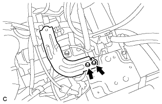
Temporarily install the No. 1 oil cooler inlet tube.
-
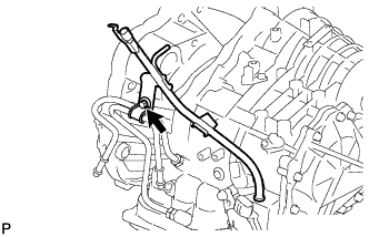
Install the oil cooler tube clamp with the bolt.
- Torque:
- 5.4 N*m { 55 kgf*cm, 48 in.*lbf }
Tech Tips
Install them so that the oil cooler tube cushion is positioned as shown in the illustration.
-
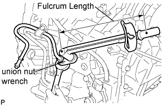
Using union nut wrench (17 mm), install the No. 1 oil cooler inlet tube while holding the union with a wrench.
- Torque:
- Without union nut wrench
- 34 N*m { 347 kgf*cm, 25 ft.*lbf }
- With union nut wrench
- 32 N*m { 326 kgf*cm, 24 ft.*lbf }
Note
-
Use a torque wrench with a fulcrum length of 380 mm (14.96 in.).
-
This torque value is effective when union nut wrench is parallel to a torque wrench.
-
-
INSTALL NO. 1 OIL COOLER OUTLET TUBE
-
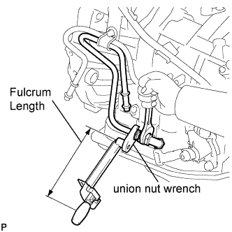
Using union nut wrench, install the No. 1 oil cooler outlet tube while holding the union with a wrench.
- Torque:
- Without union nut wrench
- 34 N*m { 347 kgf*cm, 25 ft.*lbf }
- With union nut wrench
- 32 N*m { 326 kgf*cm, 24 ft.*lbf }
Note
-
Use a torque wrench with a fulcrum length of 380 mm (14.96 in.).
-
This torque value is effective when union nut wrench is parallel to a torque wrench.
-
-
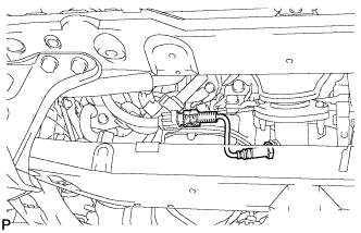
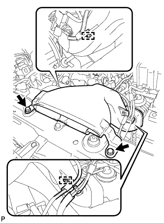
INSTALL NO. 1 TRANSMISSION CONTROL CABLE BRACKET
-
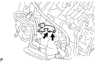
Install the No. 1 transmission control cable bracket with the 2 bolts.
- Torque:
- 12 N*m { 122 kgf*cm, 9 ft.*lbf }
-
-
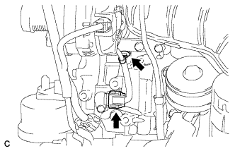
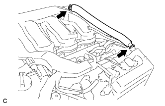
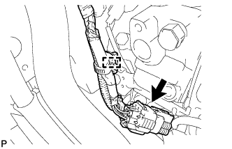
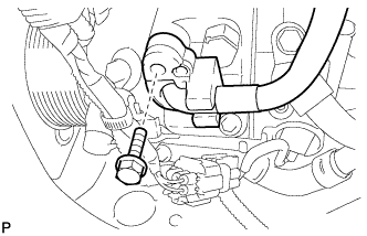
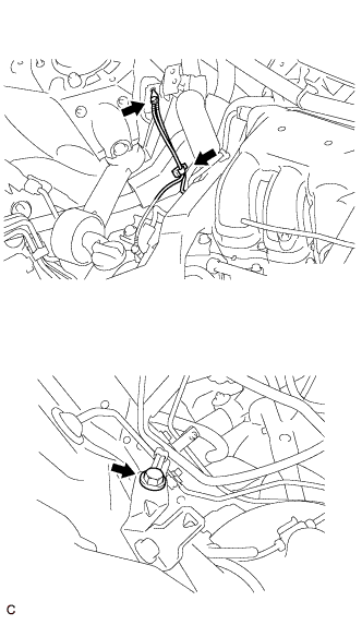
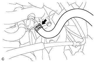
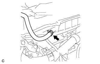
CONNECT BREATHER PLUG HOSE
-
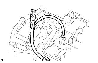
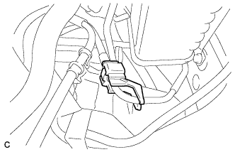
Connect the breather plug hose to the oil filler tube.
-
-
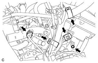
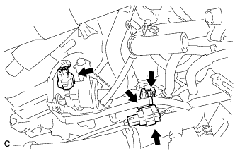
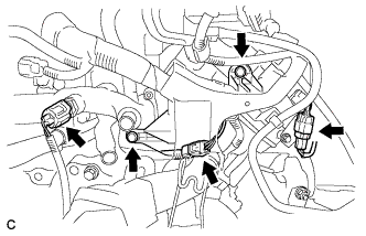
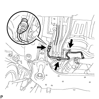
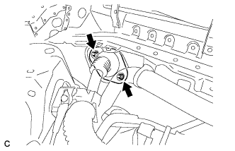
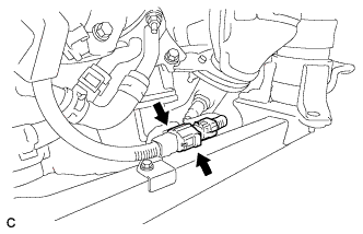
CONNECT CONNECTORS
-
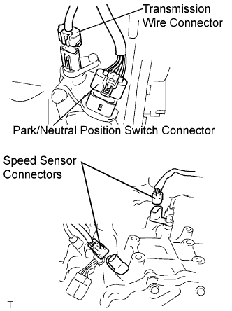
Connect the transmission wire connector.
-
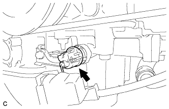
Connect the park/neutral position switch connector.
-
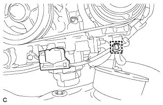
Connect the 2 speed sensor connectors.
-
-
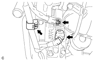
CONNECT WIRE HARNESS
-
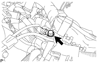
Connect the wire harness with the bolt.
- Torque:
- 13 N*m { 133 kgf*cm, 10 ft.*lbf }
-
-
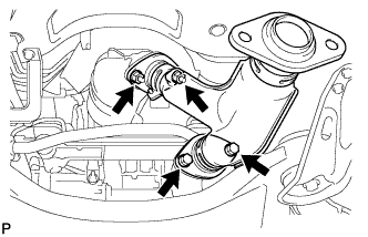
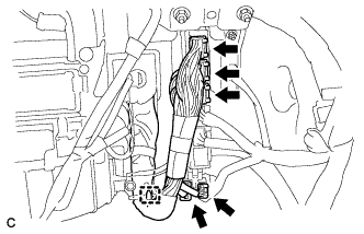
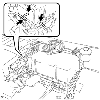
INSTALL WIRE HARNESS CLAMP
-
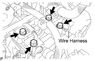
Install the 3 clamps and 3 bolts.
- Torque:
- 8.4 N*m { 86 kgf*cm, 74 in.*lbf }
-
Connect the wire harness with the bolt.
- Torque:
- 13 N*m { 133 kgf*cm, 10 ft.*lbf }
-
-
INSTALL NO. 2 TRANSMISSION CONTROL CABLE BRACKET
-
Install the No. 2 transmission control cable bracket with the bolt.
- Torque:
- 12 N*m { 122 kgf*cm, 9 ft.*lbf }
-
-
INSTALL FRONT DRIVE SHAFT ASSEMBLY LH
-
Align the shaft splines and install the drive shaft assembly LH with a brass bar and hammer.
Note
-
Set the shaft snap ring with the opening facing down.
-
Be careful not to damage the drive shaft dust cover, boot, or oil seal.
-
Move the drive shaft assembly while keeping it level.
-
-
-
INSTALL FRONT DRIVE SHAFT ASSEMBLY RH (for 4WD)
Tech Tips
Perform the same procedure as for the LH side.
-
INSTALL TRANSVERSE ENGINE MOUNTING BRACKET
-
Install the transverse engine mount bracket with the 3 bolts.
- Torque:
- 64 N*m { 650 kgf*cm, 47 ft.*lbf }
-
-
INSTALL FRONT ENGINE MOUNTING INSULATOR ASSEMBLY
-
Temporarily install the front engine mounting insulator assembly with the nut.
-
-
INSTALL TRANSVERSE ENGINE MOUNTING INSULATOR
-
Temporarily install the transverse engine mounting insulator with the nut.
-
-
INSTALL TRANSVERSE ENGINE MOUNTING INSULATOR
-
Temporarily install the transverse mounting insulator with the nut.
-
-
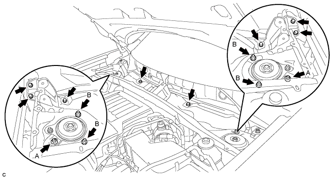
INSTALL FRONT FRAME ASSEMBLY
-
Temporarily install the engine assembly with transaxle with the 9 nuts and 2 bolts.
-
Tighten the 4 nuts.
- Torque:
- A
- 87 N*m { 887 kgf*cm, 64 ft.*lbf }
- B
- 52 N*m { 525 kgf*cm, 38 ft.*lbf }
-
Tighten the 4 nuts.
- Torque:
- A
- 95 N*m { 969 kgf*cm, 70 ft.*lbf }
- B
- 87 N*m { 887 kgf*cm, 64 ft.*lbf }
-
Tighten the 4 nuts.
- Torque:
- A
- 95 N*m { 969 kgf*cm, 70 ft.*lbf }
- B
- 87 N*m { 887 kgf*cm, 64 ft.*lbf }
-
Tighten the 2 bolts.
- Torque:
- 78 N*m { 795 kgf*cm, 58 ft.*lbf }
-
Connect the duty vacuum switching valve connector and clamp.
-
Install the 5 hole plugs.
-
-
INSTALL POWER STEERING LINK ASSEMBLY (for 4WD)
-
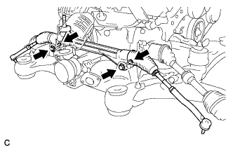
Install the power steering link assembly with the 2 bolts and 2 nuts.
- Torque:
- 70 N*m { 713 kgf*cm, 51 ft.*lbf }
Note
-
Make sure to tighten the bolts starting from the left side of the vehicle.
-
Because the nut has its own stopper, do not turn the nut. Tighten the bolt with the nut fixed.
-
-
INSTALL FRONT STABILIZER BAR
-
Install the front stabilizer bar by inserting it from the right side of the vehicle.
-
-
REMOVE ENGINE HANGERS
-
Remove the 4 bolts and 2 engine hangers.
-
-
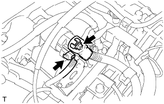
INSTALL MANIFOLD STAY
-
Install the bolt, nut, and manifold stay.
- Torque:
- 34 N*m { 347 kgf*cm, 25 ft.*lbf }
-
-
INSTALL STARTER ASSEMBLY
-
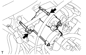
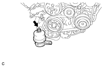
Install the starter assembly with the 2 bolts.
- Torque:
- 37 N*m { 377 kgf*cm, 27 ft.*lbf }
-
Connect the starter connector.
-
Connect the starter wire with the nut and cover the nut with the cap.
- Torque:
- 9.8 N*m { 100 kgf*cm, 87 in.*lbf }
-
-
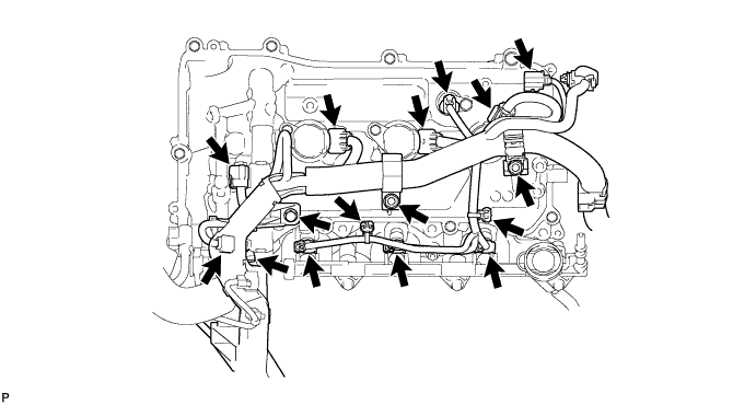
INSTALL ENGINE WIRE (for LHD)
-
Install the 3 bolts.
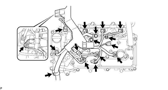
- Torque:
- 8.3 N*m { 85 kgf*cm, 74 in.*lbf }
-
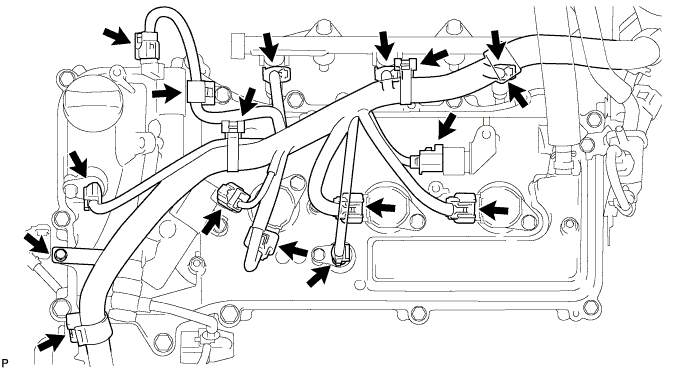
Connect the 2 clamps, 3 ignition coil assembly connectors, 2 camshaft timing oil control valve assembly connectors, 2 VVT sensor connectors, 3 injector assembly connectors, and radio setting condenser connector.
-
Install the bolt and 2 nuts.
- Torque:
- 8.3 N*m { 85 kgf*cm, 74 in.*lbf }
-
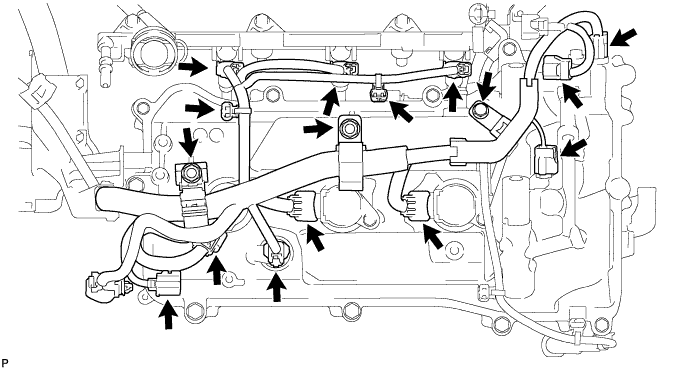
Connect the 2 clamps, 3 ignition coil assembly connectors, 2 camshaft timing oil control valve assembly connectors, 2 VVT sensor connectors and 3 injector connectors.
-
Connect the air fuel ratio sensor connector.
-
Connect the 2 clamps, engine coolant temperature sensor connector and knock control sensor wire connector.
-
Install the ground cable bolt.
-
Connect the purge VSV connector, air fuel ratio sensor connector and 2 clamps.
-
Install the nut.
- Torque:
- 9.8 N*m { 100 kgf*cm, 87 in.*lbf }
-
Connect the generator assembly connector and clamp.
-
Connect the crankshaft position sensor connector and clamp.
-
Connect the oil pressure switch assembly connector.
-
Connect the oil pressure switch assembly cover.
-
-
INSTALL ENGINE WIRE (for RHD)
-
Install the bolt.
- Torque:
- 8.3 N*m { 85 kgf*cm, 74 in.*lbf }
-
Connect the 4 clamps, radio setting condenser connector, 3 ignition coil assembly connectors, 2 camshaft timing oil control valve assembly connectors, 2 VVT sensor connectors, and 3 injector assembly connectors.
-
Install the bolt and 2 nuts.
- Torque:
- 8.3 N*m { 85 kgf*cm, 74 in.*lbf }
-
Connect the 2 clamps, radio setting condenser connector, 3 ignition coil assembly connectors, 2 camshaft timing oil control valve assembly connectors, 2 VVT sensor connectors and 3 injector connectors.
-
Connect the air fuel ratio sensor connector.
-
Connect the clamp, engine coolant temperature sensor connector and knock control sensor wire connector.
-
Install the 2 bolts.
-
Connect the purge VSV connector, air fuel ratio sensor connector and 2 clamps.
-
Install the nut.
- Torque:
- 9.8 N*m { 100 kgf*cm, 87 in.*lbf }
-
Connect the generator assembly connector and clamp.
-
Connect the crankshaft position sensor connector and clamp.
-
Connect the oil pressure switch assembly connector.
-
Connect the oil pressure switch assembly cover.
-
-
INSTALL INTAKE AIR SURGE TANK ASSEMBLY
Note
DO NOT apply oil to the bolts and nuts listed below:
Tightening Parts Intake air surge tank assembly and Intake manifold No. 1 surge tank stay and Cylinder head cover sub-assembly No. 1 surge Tank Stay and Intake air surge tank assembly Throttle body bracket and Cylinder head cover sub-assembly Throttle body bracket and Intake air surge tank assembly
-
Install a new gasket to the intake air surge tank.
-
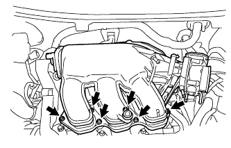
Using a 5 mm hexagon socket wrench, install the 4 bolts and 2 nuts.
- Torque:
- Bolt
- 18 N*m { 184 kgf*cm, 13 ft.*lbf }
- Nut
- 16 N*m { 163 kgf*cm, 12 ft.*lbf }
-
Install the throttle body bracket, No. 1 surge tank stay and 4 bolts.
- Torque:
- 21 N*m { 214 kgf*cm, 15 ft.*lbf }
-
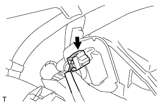
Connect the connector.
-
Connect the No. 1 ventilation hose.
-
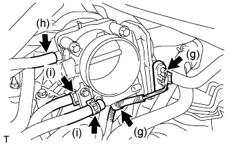
Install the clamp and connect the throttle with motor body assembly connector.
-
Connect the vapor feed hose.
-
Connect the 2 water by-pass hoses to the throttle with motor body assembly.
-
-
INSTALL VENTILATION HOSE
-
Using pliers, grip the claws of the 2 clips and slide the 2 clips to the intake air surge tank assembly and ventilation valve.
-
-
TEMPORARILY TIGHTEN COMPRESSOR AND MAGNETIC CLUTCH
-
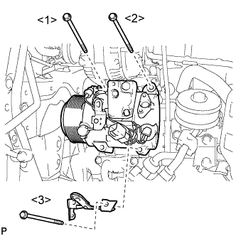
Temporarily install the compressor and magnetic clutch with the bolts.
Tech Tips
Temporarily tighten the bolts in the order shown in the illustration.
-
-
INSTALL COMPRESSOR AND MAGNETIC CLUTCH
-
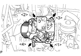
Install the compressor and magnetic clutch with the 4 bolts.
- Torque:
- 25 N*m { 255 kgf*cm, 18 ft.*lbf }
Note
Tighten the bolts in the order shown in the illustration to install the compressor and magnetic clutch.
-
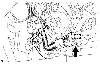
Engage each clamp.
-
Connect the connector.
-
Engage the clamp.
-
Connect the connector.
-
-
INSTALL ENGINE ASSEMBLY WITH TRANSAXLE
-
Set the engine assembly with transaxle on the engine lifter.
-
Install the engine assembly to the vehicle.
-
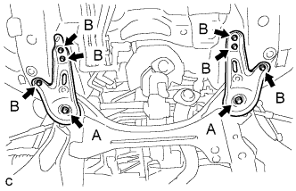
Install the frame side rail plates RH and LH with the 6 bolts and 2 nuts.
- Torque:
- A
- 85 N*m { 867 kgf*cm, 63 ft.*lbf }
- B
- 32 N*m { 327 kgf*cm, 24 ft.*lbf }
-
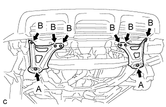
Install the front suspension member rear braces RH and LH with the 6 bolts and 2 nuts.
- Torque:
- A
- 85 N*m { 867 kgf*cm, 63 ft.*lbf }
- B
- 32 N*m { 327 kgf*cm, 24 ft.*lbf }
-
-
CONNECT SUCTION HOSE SUB-ASSEMBLY
-
Remove the attached vinyl tape from the hose.
-
Apply sufficient compressor oil to a new O-ring and the fitting surface of the compressor and magnetic clutch.
Compressor oil ND-OIL 8 or equivalent -
Install the O-ring onto the suction hose sub-assembly.
-
Install the suction hose sub-assembly onto the compressor and magnetic clutch with the bolt.
- Torque:
- 9.8 N*m { 100 kgf*cm, 87 in.*lbf }
-
-
CONNECT DISCHARGE HOSE SUB-ASSEMBLY
-
Remove the attached vinyl tape from the hose.
-
Apply sufficient compressor oil to a new O-ring and the fitting surface of the compressor and magnetic clutch.
Compressor oil ND-OIL 8 or equivalent -
Install the O-ring onto the discharge hose sub-assembly.
-
Install the discharge hose sub-assembly onto the compressor and magnetic clutch with the bolt.
- Torque:
- 9.8 N*m { 100 kgf*cm, 87 in.*lbf }
-
-
INSTALL STEERING INTERMEDIATE SHAFT SUB-ASSEMBLY
-
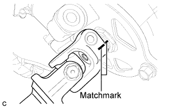
Align the matchmarks on the steering intermediate shaft sub-assembly and the steering column assembly.
-
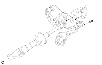
Install a new bolt.
- Torque:
- 35 N*m { 360 kgf*cm, 26 ft.*lbf }
-
-
INSTALL FRONT AXLE ASSEMBLY LH
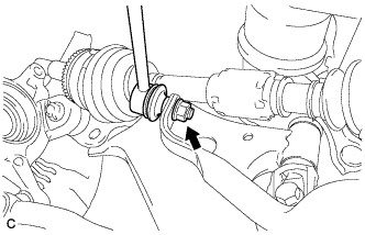
-
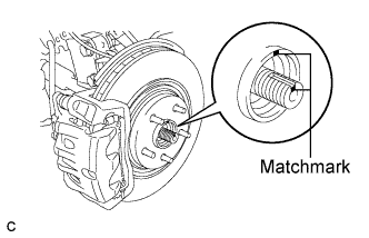
Align the matchmarks and install the front drive shaft assembly to the front axle hub sub-assembly.
-
-
INSTALL FRONT AXLE ASSEMBLY RH
Tech Tips
Use the same procedure described for the LH side.
-
INSTALL NO. 1 FRONT SUSPENSION LOWER ARM LH
-
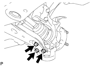
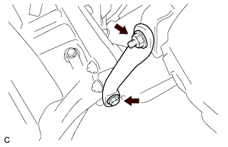
Install the front lower suspension arm to the front lower ball joint with the bolt and 2 nuts.
- Torque:
- 92 N*m { 938 kgf*cm, 68 ft.*lbf }
-
-
INSTALL NO. 1 FRONT SUSPENSION LOWER ARM RH
Tech Tips
Use the same procedure described for the LH side.
-
CONNECT TIE ROD ASSEMBLY LH
-
Connect the tie rod assembly LH to the steering knuckle with the nut.
- Torque:
- 49 N*m { 500 kgf*cm, 36 ft.*lbf }
-
Install a new cotter pin.
Note
Further tighten the nut up to 60° if the holes for the cotter pin are not aligned.
-
-
CONNECT TIE ROD ASSEMBLY RH
Tech Tips
Perform the same procedure as for the LH side.
-
INSTALL FRONT SPEED SENSOR LH
-
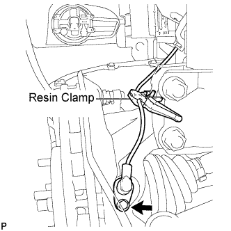
Install the resin clamp and front speed sensor with the bolt.
- Torque:
- 8.0 N*m { 82 kgf*cm, 71 in.*lbf }
Note
-
Prevent foreign matter from attaching to the sensor tip.
-
Firmly insert the sensor body into the knuckle before tightening the bolt.
-
After installing the sensor to the knuckle, make sure that there is no clearance between the sensor stay and knuckle. Also make sure that no foreign matter is stuck between the parts.
-
To prevent interference between the sensor and magnetic rotor, do not rotate the sensor body during or after the insertion of the sensor body to the knuckle.
-
-
INSTALL FRONT SPEED SENSOR RH
Tech Tips
Use the same procedure described for the LH side.
-
INSTALL FRONT AXLE HUB NUT LH
-
Clean the threaded parts on the drive shaft and axle hub nut using a non-residue solvent.
Tech Tips
-
Be sure to perform this work for a new drive shaft.
-
Keep the threaded parts free of oil and foreign objects.
-
-
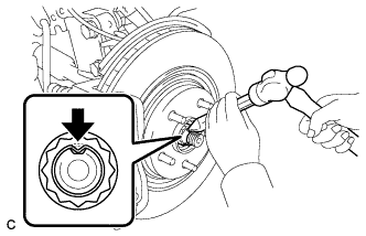
Using a socket wrench (30 mm), install a new axle hub nut.
- Torque:
- 294 N*m { 2996 kgf*cm, 216 ft.*lbf }
-
Using a chisel and hammer, stake the front axle hub nut.
-
-
INSTALL FRONT AXLE HUB NUT RH
Tech Tips
Perform the same procedure for the LH side.
-
INSTALL FRONT STABILIZER LINK ASSEMBLY LH
-
Install the front stabilizer link assembly LH with the nut.
- Torque:
- 74 N*m { 755 kgf*cm, 55 ft.*lbf }
Tech Tips
If the ball joint turns together with the nut, use a hexagon wrench (6 mm) to hold the stud bolt.
-
-
INSTALL FRONT STABILIZER LINK ASSEMBLY RH
Tech Tips
Use the same procedure described for the LH side.
-
INSTALL FRONT EXHAUST PIPE ASSEMBLY
-
Install a new gasket to the front exhaust pipe assembly.
-
Install the front exhaust pipe assembly with 2 new nuts.
- Torque:
- 56 N*m { 571 kgf*cm, 41 ft.*lbf }
-
Connect the heated oxygen sensor (for bank 2 sensor 2) connector.
-
-
INSTALL FRONT NO. 3 EXHAUST PIPE SUB-ASSEMBLY
-
Install 2 new gaskets to the front No. 3 exhaust pipe sub-assembly.
-
Install the front No. 3 exhaust pipe sub-assembly with 2 new nuts and the 2 bolts.
- Torque:
- 56 N*m { 571 kgf*cm, 41 ft.*lbf }
-
Install the 3 clamps and connect the heated oxygen sensor (for bank 1 sensor 2) connector.
-
Tighten the front exhaust pipe assembly bolt.
- Torque:
- 21 N*m { 214 kgf*cm, 15 ft.*lbf }
-
-
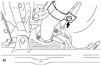
INSTALL CENTER EXHAUST PIPE ASSEMBLY
-
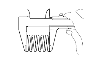
Using vernier calipers, measure the free length of the compression spring.
Minimum 41.5 mm (1.63 in.) Tech Tips
If the length is less than the minimum, replace the compression spring.
-
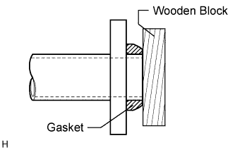
Using a plastic-faced hammer and wooden block, tap in a new gasket until its surface is flush with the front No. 3 exhaust pipe sub-assembly.
Note
-
Tap in the gasket in the correct direction.
-
Do not reuse the removed gasket.
-
Do not push in the gasket while installing the center exhaust pipe assembly.
-
-
Connect the 3 exhaust pipe supports, and install the center exhaust pipe assembly.
-
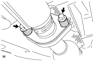
Install the 2 compression springs and 2 bolts.
- Torque:
- 48 N*m { 489 kgf*cm, 35 ft.*lbf }
-
-
INSTALL TAIL EXHAUST PIPE ASSEMBLY
-
Using vernier calipers, measure the free length of the compression spring.
Minimum 40.5 mm (1.59 in.) Tech Tips
If the length is less than the minimum, replace the compression spring.
-
Using a plastic-faced hammer and wooden block, tap in a new gasket until its surface is flush with the center exhaust pipe assembly.
Note
-
Tap in the gasket in the correct direction.
-
Do not reuse the removed gasket.
-
Do not push in the gasket while installing the tail exhaust pipe assembly.
-
-
Connect the exhaust pipe support, and install the tail exhaust pipe assembly.
-
Install the 2 compression springs and 2 bolts.
- Torque:
- 48 N*m { 489 kgf*cm, 35 ft.*lbf }
-
-
TEMPORARILY TIGHTEN PROPELLER WITH CENTER BEARING SHAFT ASSEMBLY
-
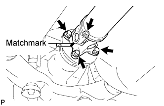
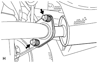
Align the matchmarks on the propeller shaft flange and differential companion flange, and connect the shaft with the 4 bolts, 4 washers and 4 nuts.
-
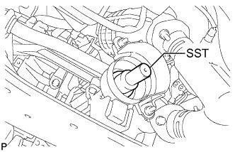
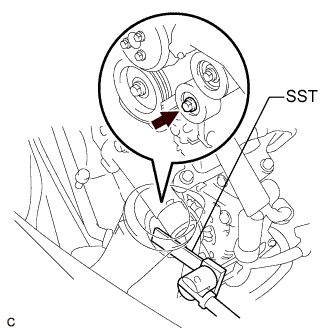
Remove SST from the transaxle.
-
Insert the yoke into the transaxle.
-
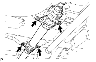
Install the 4 adjusting shims and propeller shaft with center bearing, and temporarily tighten the 4 bolts.
-
Tighten the 4 bolts.
- Torque:
- 74 N*m { 750 kgf*cm, 54 ft.*lbf }
-
-
FULLY TIGHTEN PROPELLER WITH CENTER BEARING SHAFT ASSEMBLY
-
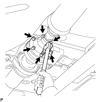
Remove the piece of cloth from the joint.
-
Using a hexagon wrench (6 mm), tighten the 6 bolts.
- Torque:
- 26 N*m { 265 kgf*cm, 19 ft.*lbf }
-
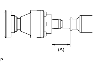
With the vehicle unloaded, adjust the dimension between the rear side of the cover and shaft as shown in the illustration.
(A) 58.0 +/- 0.5 mm (2.283 +/- 0.02 in.) -
Under the same condition as above, adjust the front and rear dimensions between the edge surface of the center support bearing and the edge surface of the cushion respectively as shown, and then tighten the bolts.
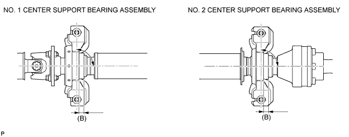
- Torque:
- 37 N*m { 375 kgf*cm, 27 ft.*lbf }
(B) 12.5 +/- 1.0 mm (0.492 +/- 0.039 in.) -
Check that the center line of the bracket is at the right angle in the shaft axial direction.
-
If any vibration or noise occurs, perform joint angle check as follows and replace the adjusting shim with a proper one.
-
Turn the propeller shaft several times by hand to stabilize the center support bearings.
-
Using a jack, raise and lower the differential to stabilize the differential mounting cushion.
-
Remove the transfer dynamic damper.
-
Using SST, measure the transfer installation angle (A) and front propeller shaft installation angle (B).
- SST
- 09370-50010
No. 1 joint angle (A) - (B) = -1.3° to -3.3° -
Using SST, measure the rear propeller shaft installation angle (C) and rear differential shaft installation angle (D).
- SST
- 09370-50010
No. 2 joint angle (C) - (D) = 1.8° to 3.5° 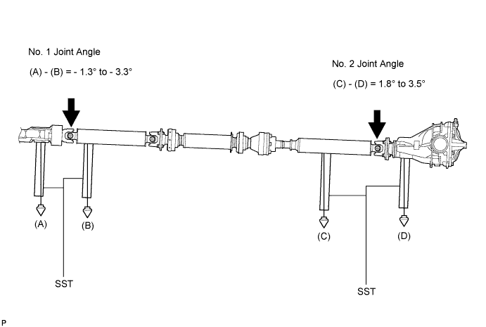
Tech Tips
If the measured angle is not within the specification, adjust it with the center support bearing adjusting shim.
Center support bearing adjusting shim thickness Thickness mm (in.) Thickness mm (in.) 3.2 (0.126) 11.0 (0.433) 4.5 (0.177) 13.5 (0.531) 6.5 (0.256) 15.5 (0.610) 9.0 (0.354) 17.5 (0.689) -
Install the transfer dynamic damper.
- Torque:
- 26 N*m { 265 kgf*cm, 19 ft.*lbf }
-
-
-
CONNECT ENGINE WIRE (for LHD)
-
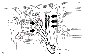
Connect the 3 ECM connectors, 2 junction block connectors and clamp.
-
Install the engine wire with the 2 nuts.
- Torque:
- 8.3 N*m { 84 kgf*cm, 73 in.*lbf }
-
Install the 2 ground cables with the 2 bolts.
- Torque:
- 8.3 N*m { 84 kgf*cm, 73 in.*lbf }
-
Connect the heated oxygen sensor clamp and connector.
-
Connect the engine wire clamp.
-
Install the ground cable with the bolt.
- Torque:
- 8.3 N*m { 84 kgf*cm, 73 in.*lbf }
-
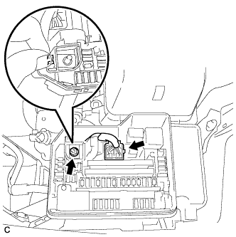
Connect the engine wire to the engine room relay block. Then, install it with the nut.
- Torque:
- 8.3 N*m { 84 kgf*cm, 73 in.*lbf }
-
Connect the engine wire connector.
-
Install the No. 1 relay block cover.
-
-
CONNECT ENGINE WIRE (for RHD)
-
Connect the 3 ECM connectors, 2 junction block connectors and clamp.
-
Install the engine wire with the 2 nuts.
- Torque:
- 8.3 N*m { 84 kgf*cm, 73 in.*lbf }
-
Install the 2 ground cables with the 2 bolts.
- Torque:
- 8.3 N*m { 84 kgf*cm, 73 in.*lbf }
-
Connect the heated oxygen sensor clamp and connector.
-
Connect the engine wire clamp.
-
Install the ground cable with the bolt.
- Torque:
- 8.3 N*m { 84 kgf*cm, 73 in.*lbf }
-
Connect the engine wire to the engine room relay block. Then, install it with the nut.
- Torque:
- 8.3 N*m { 84 kgf*cm, 73 in.*lbf }
-
Connect the engine wire connector.
-
Install the No. 1 relay block cover.
-
-
CONNECT TRANSMISSION CONTROL CABLE ASSEMBLY
-
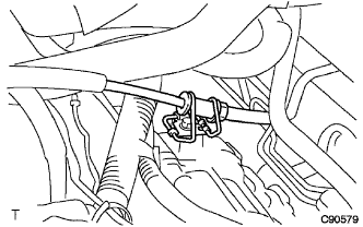
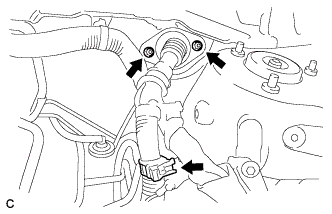
Connect the transmission control cable assembly to the control cable clamp.
-
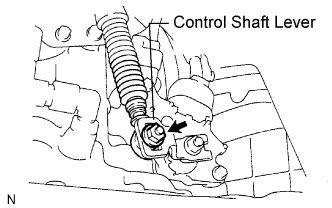
Install the transmission control cable assembly to the control shaft lever with the nut.
- Torque:
- 12 N*m { 122 kgf*cm, 9 ft.*lbf }
-
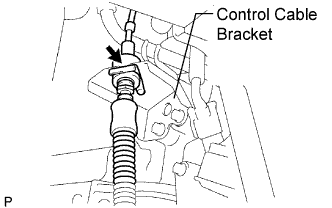
Connect the transmission control cable assembly to the bracket with a new clip.
-
-
CONNECT FUEL TUBE SUB-ASSEMBLY
-
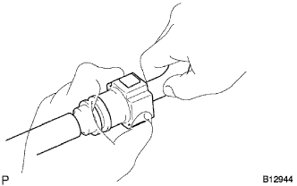
Push in the fuel tube connector to the fuel pipe until the fuel tube makes a "click" sound.
Note
-
Check for damage or dirt and foreign objects on the connected part of the pipe.
-
Check if the pipe and the connector are securely connected by trying to pull them apart.
-
-
Install the No. 1 fuel pipe clamp.
-
-
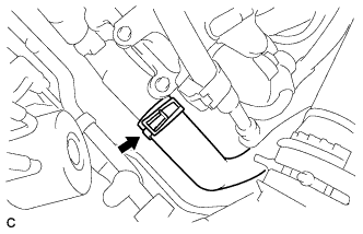
CONNECT OIL COOLER OUTLET HOSE
-
Using pliers, grip the claws of the clip and slide the clip to connect the oil cooler outlet hose.
-
-
CONNECT OIL COOLER INLET HOSE
-
Using pliers, grip the claws of the clip and slide the clip to connect the No. 2 transmission oil cooler hose.
-
-
CONNECT HEATER WATER HOSE INLET B
-
Using pliers, grip the claws of the clip and slide the clip to connect the heater water inlet hose B to water outlet.
-
-
CONNECT HEATER WATER HOSE OUTLET B
-
Using pliers, grip the claws of the clip and slide the clip to connect the heater water outlet hose B to water inlet.
-
-
INSTALL NO. 1 RADIATOR HOSE
-
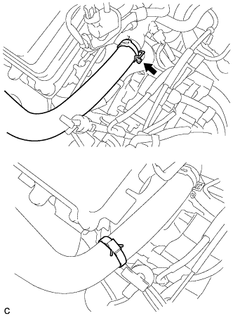
Using pliers, grip the claws of the clip and slide the clip to connect the No. 1 radiator hose to the water outlet.
-
Install the clamp with the air fuel ratio sensor connector.
-
-
INSTALL NO. 2 RADIATOR HOSE
-
Using pliers, grip the claws of the clip and slide the clip to connect the No. 2 radiator hose to the water inlet.
-
-
CONNECT UNION TO CHECK VALVE HOSE
-
Using pliers, grip the claws of the clip and slide the clip to connect the union to check valve hose to the intake air surge tank assembly.
-
-
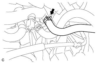
CONNECT NO. 1 FUEL VAPOR FEED HOSE
-
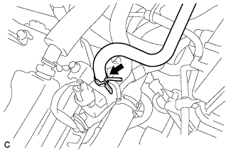
Install the clamp and connect the No. 1 fuel vapor feed hose.
-
-
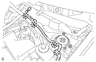
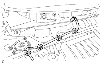
INSTALL ENGINE MOVING CONTROL ROD
-
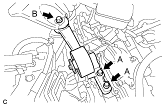
Temporarily install the engine moving control rod with the 3 bolts.
-
First install bolts A, and then bolt B.
- Torque:
- 38 N*m { 388 kgf*cm, 28 ft.*lbf }
-
-
INSTALL NO. 2 ENGINE MOUNTING STAY RH
-
Temporarily install the No. 2 engine mounting stay RH with the bolt.
- Torque:
- 38 N*m { 388 kgf*cm, 28 ft.*lbf }
-
Tighten the 2 nuts.
- Torque:
- 23 N*m { 235 kgf*cm, 17 ft.*lbf }
-
-
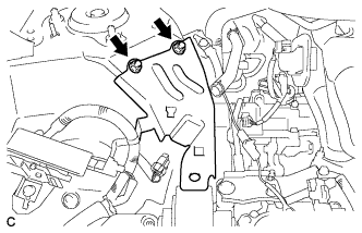
INSTALL RESERVOIR BRACKET (for LHD)
-
Install the reservoir bracket with the 2 bolts.
- Torque:
- 9.0 N*m { 92 kgf*cm, 80 in.*lbf }
-
-
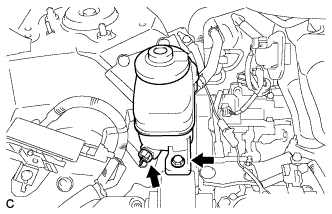
INSTALL BRAKE MASTER CYLINDER RESERVOIR ASSEMBLY (for LHD)
-
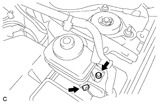
Install the brake master cylinder reservoir assembly with the bolt.
- Torque:
- 9.0 N*m { 92 kgf*cm, 80 in.*lbf }
-
Connect the level warning switch connector.
-
-
INSTALL RESERVOIR BRACKET (for RHD)
-
Install the reservoir bracket with the 2 bolts.
- Torque:
- 19.0 N*m { 193 kgf*cm, 14 ft.*lbf }
-
-
INSTALL BRAKE MASTER CYLINDER RESERVOIR ASSEMBLY (for RHD)
-
Install the brake master cylinder reservoir assembly with the bolt.
- Torque:
- 9.0 N*m { 92 kgf*cm, 80 in.*lbf }
-
Connect the level warning switch connector.
-
-
INSTALL AIR CLEANER BRACKET
-
Install the 2 bolts and air cleaner bracket.
- Torque:
- 12 N*m { 123 kgf*cm, 9 ft.*lbf }
-
-
INSTALL BATTERY
-
Install the battery tray and battery.
-
Install the battery clamp with the bolt and nut.
- Torque:
- Bolt
- 5.4 N*m { 55 kgf*cm, 48 in.*lbf }
- Nut A
- 5.4 N*m { 55 kgf*cm, 48 in.*lbf }
- Nut B
- 13 N*m { 131 kgf*cm, 9 ft.*lbf }
- Nut C
- 6.4 N*m { 64 kgf*cm, 57 in.*lbf }
-
Install the positive battery terminal and nut.
-
Connect the negative battery terminal, and tighten the nut.
-
-
CONNECT CABLE TO NEGATIVE BATTERY TERMINAL
CAUTION:
Wait at least 90 seconds after disconnecting the cable from the negative (-) battery terminal to prevent airbag and seat belt pretensioner activation.
Note
When disconnecting the cable, some systems need to be initialized after the cable is reconnected Click here.
-
INSTALL AIR CLEANER CASE SUB-ASSEMBLY
-
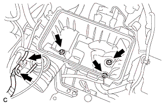
Install the air cleaner case with the 3 bolts.
- Torque:
- 5.0 N*m { 51 kgf*cm, 44 in.*lbf }
-
Connect the hose and connector.
-
-
INSTALL AIR CLEANER FILTER ELEMENT SUB-ASSEMBLY
-
Install the air cleaner filter element sub-assembly.
-
-
INSTALL AIR CLEANER CAP SUB-ASSEMBLY
-
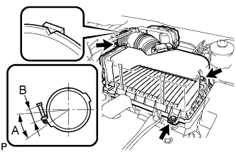
Install the air cleaner filter element, align the groove on the air cleaner hose with the throttle body alignment tab and tighten the clamp as shown in the illustration.
Tech Tips
-
A = 30°
-
B = 11 to 14 mm (0.433 in. to 0.551 in.)
-
-
Install the air cleaner cap with the 2 bolts and clips.
- Torque:
- 5.0 N*m { 51 kgf*cm, 44 in.*lbf }
-
Connect the 3 vacuum hoses.
-
Connect the mass air flow meter connector.
-
Connect the No. 2 ventilation hose and fuel vapor feed hose assembly.
-
-
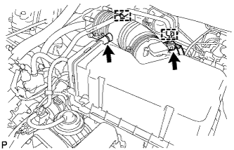
INSTALL NO. 1 AIR CLEANER INLET
-
Install the No. 1 air cleaner inlet with the 2 bolts.
- Torque:
- 7.0 N*m { 71 kgf*cm, 62 in.*lbf, [A] }
- Torque:
- 5.0 N*m { 51 kgf*cm, 44 in.*lbf, [B] }
-
Connect the 2 vacuum hoses.
-
-
INSTALL NO. 2 AIR CLEANER INLET
-
Install the No. 2 air cleaner inlet with the 2 bolts.
- Torque:
- 7.0 N*m { 71 kgf*cm, 62 in.*lbf }
-
Connect the 2 vacuum hoses and harness clamps.
-
-
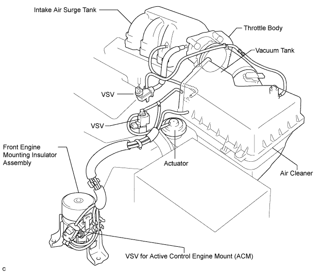
CONNECT VACUUM HOSES
-
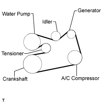
INSTALL V-RIBBED BELT
-
Install the V-ribbed belt.
-
Using SST, turn the V-ribbed belt tensioner assembly counterclockwise and remove the bar.
- SST
- 09961-00950
-
If it is difficult to install the V-ribbed belt, perform the following procedure:
-
Put the V-ribbed belt on every pulley except the tensioner pulley as shown in the illustration.
-
Release the V-ribbed belt tension by turning the V-ribbed belt tensioner assembly counterclockwise, and put the V-ribbed belt on the V-ribbed belt tensioner assembly pulley.
Note
-
Put the backside of the V-ribbed belt on the V-ribbed belt tensioner assembly pulley and No. 2 idler pulley sub-assembly.
-
Check that the V-ribbed belt is properly set to each pulley.
-
-
After installing the V-ribbed belt, check that it fits properly in the ribbed grooves. Confirm that the V-ribbed belt has not slipped out of the grooves on the bottom of the crankshaft pulley by hand.
-
-
-
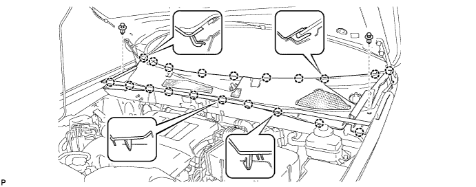
INSTALL OUTER COWL TOP PANEL SUB-ASSEMBLY (for LHD)
-
Install the front outer cowl top panel sub-assembly with the 8 bolts and 6 nuts.
- Torque:
- Bolt
- 8.8 N*m { 90 kgf*cm, 78 in.*lbf }
- Nut A
- 8.8 N*m { 90 kgf*cm, 78 in.*lbf }
- Nut B
- 85 N*m { 867 kgf*cm, 63 ft.*lbf }
-
Install the 4 clips.
-
-
INSTALL OUTER COWL TOP PANEL SUB-ASSEMBLY (for RHD)
-
Install the front outer cowl top panel sub-assembly with the 8 bolts and 6 nuts.
- Torque:
- Bolt
- 8.8 N*m { 90 kgf*cm, 78 in.*lbf }
- Nut A
- 8.8 N*m { 90 kgf*cm, 78 in.*lbf }
- Nut B
- 85 N*m { 867 kgf*cm, 63 ft.*lbf }
-
Install the 4 clips.
-
-
INSTALL WINDSHIELD WIPER MOTOR AND LINK ASSEMBLY
-
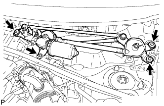
Install the windshield wiper motor and link assembly with the 4 bolts.
- Torque:
- 7.0 N*m { 71 kgf*cm, 62 in.*lbf }
-
Connect the connector.
-
-
INSTALL COWL TOP VENTILATOR LOUVER SUB-ASSEMBLY
-
Engage the 20 claws.
-
Install the cowl top ventilator louver sub-assembly with the 2 clips.
-
Engage the 2 claws and connect the front fender to cowl side seal LH.
-
Engage the 2 claws and connect the front fender to cowl side seal RH.
-
-
INSTALL FRONT WIPER ARM AND BLADE ASSEMBLY RH
-
Operate the wiper and stop the windshield wiper motor at the automatic stop position.
-
When reinstalling:
-
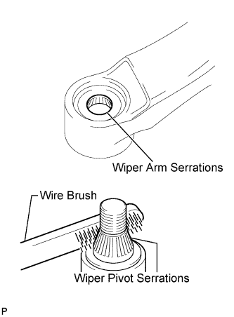
Clean the wiper arm serrations.
-
Clean the wiper pivot serrations with a wire brush.
-
-
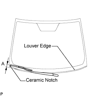
Install the front wiper arm and blade assembly RH with the nut to the position shown in the illustration.
- Torque:
- 24 N*m { 245 kgf*cm, 18 ft.*lbf }
Tech Tips
Hold the wiper arm by hand when tightening the nut.
Area Measurement A 25.6 mm (1.00 in.)
-
-
INSTALL FRONT WIPER ARM AND BLADE ASSEMBLY LH
-
Operate the wiper and stop the windshield wiper motor at the automatic stop position.
-
When reinstalling:
-
Clean the wiper arm serrations.
-
Clean the wiper pivot serrations with a wire brush.
-
-
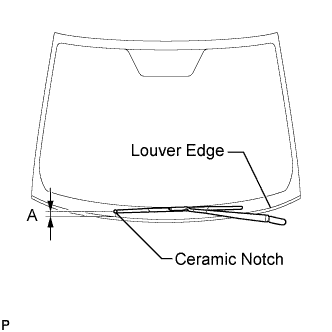
Install the front wiper arm and blade assembly LH with the nut to the position shown in the illustration.
- Torque:
- 24 N*m { 245 kgf*cm, 18 ft.*lbf }
Tech Tips
Hold the wiper arm by hand when tightening the nut.
Area Measurement A 31.9 mm (1.26 in.) -
Operate the front wipers while spraying washer fluid onto the windshield glass. Make sure that the front wipers function properly and the wipers do not come into contact with the vehicle body.
-
-
INSTALL FRONT WHEELS
- Torque:
- 103 N*m { 1050 kgf*cm, 76 ft.*lbf }
-
ADD ENGINE OIL
-
Add clean engine oil and install the oil filler cap.
Engine oil Oil Grade Oil Viscosity (SAE) .API grade SL and energy-conserving
.API grade SM and energy-conserving
.ILSAC multigrade engine oil
10W-30 API grade SL 15W-40 API grade SM 20W-50 Standard capacity (w/ Oil Cooler): Item Standard Condition Drain and refill with oil filter change 6.1 liters (6.4 US qts, 5.4 lmp. qts) Drain and refill without oil filter change 5.7 liters (6.0 US qts, 5.0 lmp. qts) Dry fill 7.1 liters (7.5 US qts, 6.2 lmp. qts) Standard capacity (w/o Oil Cooler): Item Standard Condition Drain and refill with oil filter change 6.1 liters (6.4 US qts, 5.4 lmp. qts) Drain and refill without oil filter change 5.7 liters (6.0 US qts, 5.0 lmp. qts) Dry fill 6.8 liters (7.2 US qts, 6.0 lmp. qts)
-
-
ADD ENGINE COOLANT
-
Tighten the radiator drain cock plug by hand.
-
Tighten the 2 cylinder block drain cock plugs.
- Torque:
- 13 N*m { 130 kgf*cm, 9 ft.*lbf, for cylinder block drain cock plugs }
-
Loosen the air drain cock plug from the water inlet housing.
-
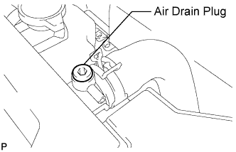
Loosen the air drain plug at the top of the radiator 3 or 4 turns.
-
Add TOYOTA Super Long Life Coolant (SLLC) to the radiator inlet opening until coolant overflows from the engine air drain cock hole. Then tighten the air drain cock plug to the water inlet housing.
- Torque:
- 13 N*m { 130 kgf*cm, 9 ft.*lbf, for air drain cock plug }
-
Continue to add TOYOTA Super Long Life Coolant (SLLC) to the radiator inlet opening until coolant overflows from the radiator air drain hole. Then close the air drain plug at the top of the radiator.
- Torque:
- 1.5 N*m { 15 kgf*cm, 13 in.*lbf, for air drain plug }
Tech Tips
If the coolant level at the radiator inlet opening drops after squeezing the No. 1 and No. 2 radiator hoses, add coolant.
-
Slowly fill the radiator with TOYOTA Super Long Life Coolant (SLLC).
Standard capacity w/o Engine oil cooler Condition Specified Condition w/ Rear Heater 11.0 liters (11.6 US qts, 9.7 Imp. qts) w/o Rear Heater 8.8 liters (9.3 US qts, 7.7 Imp. qts) w/ Engine oil cooler Condition Specified Condition w/ Rear Heater 11.7 liters (12.4 US qts, 10.3 Imp. qts) w/o Rear Heater 9.5 liters (10.1 US qts, 8.4 Imp. qts) Tech Tips
-
TOYOTA vehicles are filled with TOYOTA SLLC at the factory. In order to avoid damage to the engine cooling system and other technical problems, only use TOYOTA SLLC or similar high quality ethylene glycol based non-silicate, non-amine, non-nitrite, non-borate coolant with long-life hybrid organic acid technology (coolant with long-life hybrid organic acid technology consists of a combination of low phosphates and organic acids).
-
Contact your TOYOTA dealer for further details.
Note
Never use water as a substitute for engine coolant.
-
-
Slowly pour coolant into the radiator reservoir tank until it reaches the FULL line.
-
Squeeze the No. 1 and No. 2 radiator hoses several times by hand, and then check the level of the coolant.
If the coolant level is low, add coolant.
-
Bleed air from the cooling system.
-
Warm up the engine until the thermostat opens. While the thermostat is open, circulate the coolant for several minutes.
Tech Tips
The thermostat open timing can be confirmed by squeezing the inlet radiator hose by hand, and checking when the engine coolant starts to flow inside the hose.
-
Maintain the engine speed at 2500 to 3000 rpm.
-
Squeeze the inlet and outlet radiator hoses several times by hand to bleed air.
CAUTION:
When squeezing the radiator hoses:
-
Wear protective gloves.
-
Be careful as the radiator hoses are hot.
-
Keep your hands away from the radiator fan.
Note
-
Make sure that the radiator reservoir still has some coolant in it.
-
If the coolant temperature gauge indicates an excessive temperature, turn off the engine and let it cool.
-
If there is not enough coolant, the engine may overheat or be seriously damaged.
-
If the radiator reservoir does not have enough coolant, perform the following: 1) stop the engine, 2) wait until the coolant has cooled down, and 3) add coolant until the reservoir is filled to the FULL line.
-
-
-
Stop the engine and wait until the engine coolant cools down.
-
Add engine coolant to the FULL line on the radiator reservoir.
-
-
INSTALL TRANSFER DRAIN PLUG
-
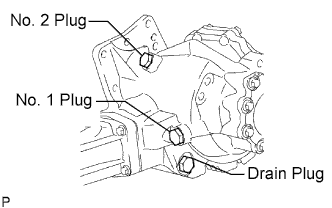
Install the transfer drain plug with a new drain gasket.
- Torque:
- 49 N*m { 500 kgf*cm, 36 ft.*lbf }
-
-
INSTALL NO. 2 TRANSFER CASE PLUG
-
Install the No. 2 transfer case plug with a new No. 2 gasket.
- Torque:
- 49 N*m { 500 kgf*cm, 36 ft.*lbf }
-
-
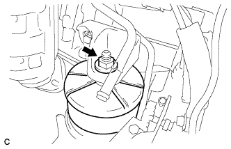
INSTALL NO. 1 TRANSFER CASE PLUG
-
Add oil up to 0 to 5 mm below the lower side of the plug hole.
Oil quantity 0.9 liters (0.95 US qts, 0.79 lmp.qts) Tech Tips
When adding oil, pour it slowly.
-
Install the No. 1 transfer case plug with a new No. 1 gasket.
- Torque:
- 49 N*m { 500 kgf*cm, 36 ft.*lbf }
-
-
ADD AUTOMATIC TRANSAXLE FLUID
-
CHECK AUTOMATIC TRANSAXLE FLUID
Tech Tips
Drive the vehicle so that the engine and transaxle are at normal operating temperature.
Fluid temperature 70 to 80°C (158 to 176°F)
-
Park the vehicle on a level surface and set the parking brake.
-
With the engine idling and the brake pedal depressed, move the shift lever to all positions from P to S1 and return to the P position.
-
Take out the dipstick and wipe it clean.
-
Put the dipstick back all the way.
-
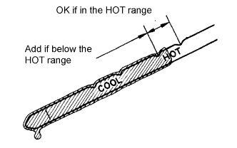
Take out the dipstick again and check that the fluid level is within the HOT range.
If the fluid level is below the HOT range, add new fluid and recheck the fluid level.
If the fluid level exceeds the HOT range, drain the fluid once, add the proper amount of new fluid and recheck the fluid level.
If there are leaks, it is necessary to repair or replace O-rings, FIPGs, oil seals, plugs and/or other parts.
-
-
INSPECT FOR FUEL LEAK
-
Check fuel pump operation.
-
Connect the intelligent tester to the DLC3.
-
Turn the ignition switch on (IG) and turn the intelligent tester main switch on.
Note
Do not start the engine.
-
Select the following menu items: DIAGNOSIS / ENHANCED OBD II / ACTIVE TEST / FUEL PUMP / SPD.
-
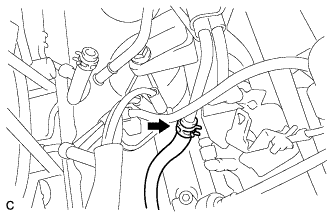
Check for pressure in the fuel inlet tube from the fuel line. Check that sounds of fuel flowing from the fuel tank can be heard. If no sounds can be heard, check the integration relay, fuel pump, ECM and wiring connectors.
-
-
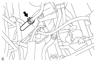
Check for fuel leaks.
-
Check that there are no fuel leaks from the fuel system after doing any maintenance or repairs. If there is a fuel leak, repair or replace parts as necessary.
-
-
Turn the ignition switch off.
-
Disconnect the intelligent tester from the DLC3.
-
-
INSPECT FOR ENGINE OIL LEAK
-
Start the engine.
-
Check for engine oil leaks from the oil filter cap and oil filter drain plug.
-
Install the oil filter element service hole cover.
-
-
INSPECT FOR COOLANT LEAK
CAUTION:
Do not remove the radiator cap while the engine and radiator are still hot. Pressurized, hot engine coolant and steam may be released and cause serious burns.
Note
Before performing each inspection, turn the A/C switch off.
-
Fill the radiator with coolant and attach a radiator cap tester.
-
Warm up the engine.
-
Using the radiator cap tester, increase the pressure inside the radiator to 118 kPa (1.2 kgf/cm2, 17 psi), and check that the pressure does not drop.
If the pressure drops, check the hoses, radiator and water pump for leaks. If no external leaks are found, check the heater core, cylinder block and cylinder head.
-
-
INSPECT FOR EXHAUST GAS LEAK
If exhaust gas is leaking, repair the leak. Replace damaged or worn parts as necessary.
-
CHECK SHIFT LEVER POSITION
-
When shifting from the P to the R position with the ignition switch on (IG) and the brake pedal depressed, make sure that the shift lever moves smoothly and moves correctly into the position.
-
Start the engine and make sure that the vehicle moves forward when shifting from the N to the D position and moves rearward when shifting to the R position. If operation cannot be done as specified, inspect the park/neutral position switch assembly and check the shift lever assembly installation condition.
-
-
CHECK AND ADJUST FRONT WHEEL ALIGNMENT
Tech Tips
-
CHECK IGNITION TIMING
-
When using the intelligent tester:
Check the ignition timing.
-
Connect the intelligent tester to the DLC3.
-
Warm up the engine.
-
Turn the tester on.
-
Enter the following menu items: Powertrain / Engine and ECT / Data List / IGN Advance.
-
Read the value displayed on the tester.
Ignition timing 8 to 12° BTDC at idle Tech Tips
Refer to the intelligent tester operator's manual for help when selecting the DATA LIST.
-
-
When not using the intelligent tester:
Check the ignition timing.
-
Warm up the engine.
-
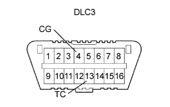
Using SST, connect terminals 13 (TC) and 4 (CG) of the DLC3.
- SST
- 09843-18040
Note
-
Confirm the terminal numbers before connecting them. Connecting the wrong terminals can damage the engine.
-
Turn off all electrical systems before connecting the terminals.
-
Perform this inspection after the cooling fan motor is turned off.
-
Remove the V-bank cover sub-assembly.
-
Pull out the red lead wire harness.
-
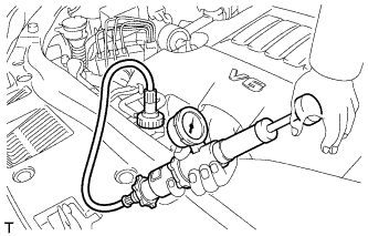
Connect the tester terminal of the timing light to the red lead wire as shown in the illustration.
Note
Use a timing light which detects the cylinder 1 ignition signal.
-
Check the ignition timing at idle.
Standard ignition timing 8 to 12° BTDC at idle Note
When checking the ignition timing, the transmission should be in the neutral position.
Tech Tips
Run the engine at 1000 to 1300 rpm for 5 seconds, and then check that the engine rpm returns to idle speed.
-
Disconnect terminals 13 (TC) and 4 (CG) of the DLC3.
-
Check the ignition timing at idle.
Standard ignition timing 7 to 24° BTDC at idle -
Confirm that the ignition timing advances immediately when the engine rpm is increased.
-
Remove the timing light from the engine.
-
-
-
CHECK ENGINE IDLE SPEED
-
When using the intelligent tester:
Check the idle speed.
-
Connect the intelligent tester to the DLC3.
-
Warm up the engine.
-
Turn the tester on.
-
Enter the following menu items: Powertrain / Engine and ECT / Data List / Engine Speed.
-
Read the value displayed on the tester.
Idle speed 600 to 700 rpm Note
-
When checking the idle speed, the transmission should be the in neutral position.
-
Check the idle speed with the cooling fan off.
-
Switch off all accessories and air conditioning before connecting the intelligent tester.
Tech Tips
Refer to the intelligent tester operator's manual for further details.
-
-
-
When not using the intelligent tester:
Check the idle speed.
-
Warm up the engine.
-
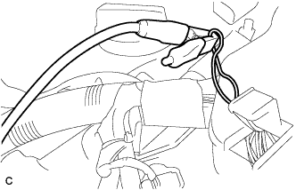
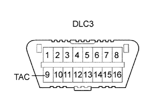
Using SST, connect the tachometer test probe to terminal 9 (TAC) of the DLC3.
- SST
- 09843-18030
-
Check the idle speed.
Standard idle speed 600 to 700 rpm
-
-
-
CHECK CO/HC
-
Start the engine.
-
Run the engine at 2500 rpm for approximately 180 seconds.
-
Insert the CO/HC meter testing probe at least 40 cm (1.3 ft.) into the tailpipe during idling.
-
Check CO/HC concentration at idle and/or 2500 rpm.
Tech Tips
Check regulations and restrictions in your area when performing 2 mode CO/HC concentration testing (engine check at both idle speed and at 2500 rpm).
If the CO/HC concentration does not comply with regulations, perform troubleshooting in the following order.
-
Check the air fuel ratio sensor and heated oxygen sensor operation.
-
See the following table for possible causes, and then inspect and repair if necessary.
CO HC Problem Cause Normal High Rough idle
-
Faulty ignitions:
-
Incorrect valve timing
-
Fouled, shorted or improperly gapped plugs
-
Incorrect valve clearance (valve lash adjuster)
-
Leaks in intake and exhaust valves
-
Leaks in cylinders
Low High Rough idle
(Fluctuating HC reading)
-
Vacuum leaks:
-
PCV hoses
-
Intake manifold
-
Throttle body assembly
-
Brake booster line
-
Lean mixture causing misfire
High High Rough idle
(Black smoke from exhaust)
-
Restricted air cleaner filter element sub-assembly
-
Plugged PCV valve
-
Faulty SFI system:
-
Faulty fuel pressure regulator
-
Defective engine coolant temperature sensor
-
Defective mass air flow meter
-
Faulty ECM
-
Faulty injector assemblies
-
Faulty throttle position sensor (built in throttle body assembly)
-
-
-
-
CHECK FUNCTION OF THROTTLE BODY ASSEMBLY
-
Listen to the throttle control motor operating sounds.
-
Turn the ignition switch on (IG).
-
When pressing the accelerator pedal position sensor lever, listen to the running motor. Make sure that no friction noise comes from the motor.
If friction noise exists, replace the throttle body.
-
-
Inspect the throttle position sensor.
-
Connect the intelligent tester to the DLC3.
-
Turn the ignition switch on (IG).
-
Check that the MIL turns off.
-
Turn the tester on.
-
Select the menu items: Powertrain / Engine and ECT / Data List / Throttle Position.
-
Check the value of throttle valve angle is within the standard range below.
Standard throttle valve opening percentage 60% or more If the percentage is less than 60%, replace the throttle body.
Note
When checking the throttle valve opening percentage, the transmission should be in neutral.
-
-
-
INSTALL FRONT FENDER APRON SEAL LH
-
Install the front fender apron seal LH with the 2 bolts and clip.
-
-
INSTALL FRONT FENDER APRON SEAL RH
-
Install the front fender apron seal RH with the 2 bolts and clip.
-
-
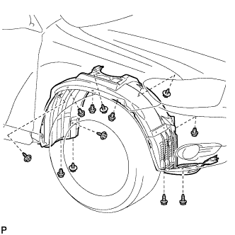
INSTALL FRONT FENDER LINER LH
-
Install the front fender liner LH with the 5 clips and 8 screws.
-
Install 2 new grommets.
-
Using a 4 mm hexagon wrench, install the 2 screws.
-
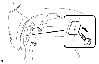
Install the screw and pin hold clip.
- Torque:
- 3.0 N*m { 31 kgf*cm, 27 in.*lbf }
-
-
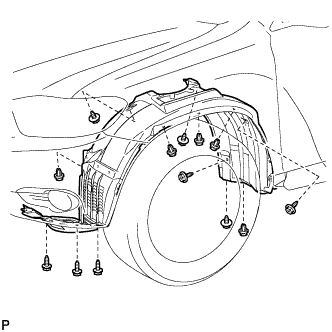
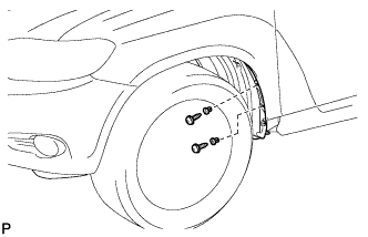
INSTALL FRONT FENDER LINER RH
-
Install the front fender liner RH with the 5 clips and 7 screws.
-
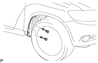
Install 2 new grommets.
-
Using a 4 mm hexagon wrench, install the 2 screws.
-
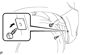
Install the screw and pin hold clip.
- Torque:
- 3.0 N*m { 31 kgf*cm, 27 in.*lbf }
-
-
INSTALL FRONT FENDER MOULDING SUB-ASSEMBLY LH
-
Clean the vehicle body surface.
-
Using a heat light, heat the vehicle body surface.
-
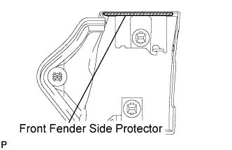
Remove the front fender side protector from the vehicle body.
-
Wipe off any tape adhesive residue with cleaner.
-
-
Clean the front fender moulding sub-assembly. (If reusing the front fender moulding sub-assembly)
-
Using a heat light, heat the front fender moulding sub-assembly.
-
Remove the front fender side protector from the front fender moulding sub-assembly.
-
Wipe off any tape adhesive residue with cleaner.
-
Install a new front fender side protector to the the front fender moulding sub-assembly.
-
-
Install 2 new No. 4 clips on the front fender moulding sub-assembly.
-
Install a new pad on the front fender moulding sub-assembly.
-
Install the front fender moulding sub-assembly.
-
Using a heat light, heat the vehicle body and the front fender moulding sub-assembly.
-
Remove the release paper from the front fender moulding sub-assembly.
Tech Tips
After removing the release paper, keep the exposed adhesive free from foreign matter.
-
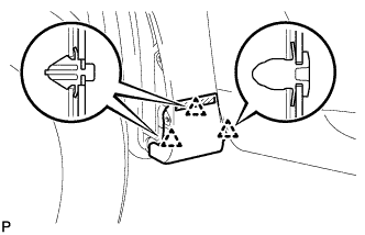
Engage the 3 clips and install the front fender moulding sub-assembly.
-
-
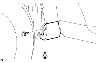
Using a 4 mm hexagon wrench, install the screw.
-
Install the clip.
-
-
INSTALL FRONT FENDER MOULDING SUB-ASSEMBLY RH
Tech Tips
Use the same procedures for the RH side and LH side.
-
INSTALL FLOOR UNDER COVER LH
-
INSTALL NO. 2 ENGINE UNDER COVER
-
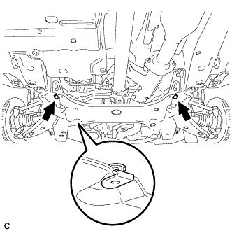
Install the No. 2 engine under cover with the 2 bolts.
-
-
INSTALL NO. 1 ENGINE UNDER COVER
-
Install the No. 1 engine under cover with the 6 bolts and 2 clips.
-
-
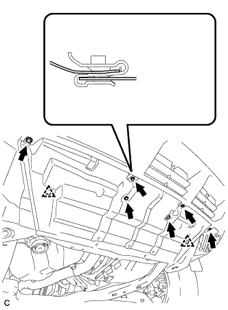
INSTALL ENGINE UNDER COVER ASSEMBLY
-

Install the engine under cover assembly with the 2 bolts, 2 screws and 5 clips.
-

Install the engine under cover assembly RR with the 2 bolts.
-
-
INSTALL V-BANK COVER SUB-ASSEMBLY
-
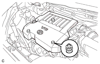
Fit the 3 retainers and install the V-bank cover.
-
-
CHECK ABS SPEED SENSOR SIGNAL
-
RESET MEMORY
Tech Tips