AUTOMATIC TRANSAXLE SYSTEM, Diagnostic DTC:P0985, P0986
| DTC Code | DTC Name |
|---|---|
| P0985 | Shift Solenoid "E" Control Circuit Low (Shift Solenoid Valve SR) |
| P0986 | Shift Solenoid "E" Control Circuit High (Shift Solenoid Valve SR) |
DESCRIPTION
Shifting from 1st to 5th is performed in combination with "ON" and "OFF" operation of the shift solenoid valves SL1, SL2, SL3, S4 and SR which are controlled by the ECM. If an open or short circuit occurs in either of the shift solenoid valves, the ECM controls the remaining normal shift solenoid valves to allow the vehicle to be operated smoothly (Fail safe function).
| DTC No. | DTC Detection Condition | Trouble Area |
|---|---|---|
| P0985 | ECM detects short in solenoid valve SR circuit 2 times when solenoid valve SR is operated (1-trip detection logic) |
|
| P0986 | ECM detects open in solenoid valve SR circuit 2 times when solenoid valve SR is not operated (1-trip detection logic) |
|
MONITOR DESCRIPTION
The ECM commands gear shifts by turning the shift solenoid valves "ON/OFF". When there is an open or short circuit in any shift solenoid valve circuit, the ECM detects the problem and illuminates the MIL and stores the DTC. And the ECM performs the fail-safe function and turns the other normal shift solenoid valves "ON/OFF" (In case of an open or short circuit, the ECM stops sending current to the circuit.) Click here.
WIRING DIAGRAM
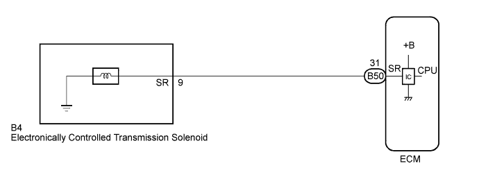
INSPECTION PROCEDURE
PROCEDURE
-
INSPECT TRANSMISSION WIRE (SR)
-
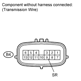
Disconnect the transmission wire connector from the transaxle.
-
Measure the resistance according to the value(s) in the table below.
Standard resistance Tester Connection Condition Specified Condition 9 (SR) - Body ground 20°C (68°F) 11 to 15 Ω
NG 
INSPECT SHIFT SOLENOID VALVE (SR) Click here
OK 
-
-
CHECK HARNESS AND CONNECTOR (TRANSMISSION WIRE - ECM)
-
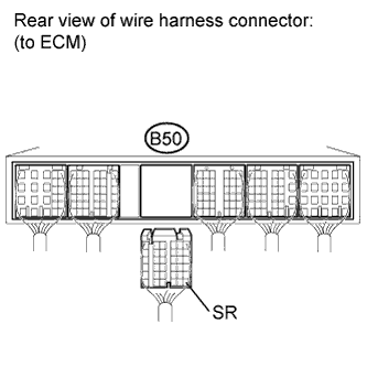
Connect the transmission wire connector to the transaxle.
-
Disconnect the ECM connector.
-
Measure the resistance according to the value(s) in the table below.
Standard resistance Tester Connection Condition Specified Condition B50-31 (SR) - Body ground 20°C (68°F) 11 to 15 Ω
NG 
REPAIR OR REPLACE HARNESS OR CONNECTOR
OK 
REPLACE ECM (for 2GR-FE) Click here
-
-
INSPECT SHIFT SOLENOID VALVE (SR)
-
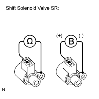
Remove the shift solenoid valve SR.
-
Measure the resistance according to the value(s) in the table below.
Standard resistance Tester Connection Condition Specified Condition Solenoid Connector (SR) - Solenoid Body (SR) 20°C (68°F) 11 to 15 Ω -
Connect the positive (+) lead to the terminal of the solenoid connector, and the negative (-) lead to the solenoid body.
OK The solenoid makes an operating sound.
NG
REPLACE SHIFT SOLENOID VALVE (SR) Click here
OK
REPAIR OR REPLACE TRANSMISSION WIRE Click here
-