PARK / NEUTRAL POSITION SWITCH INSTALLATION
-
INSTALL PARK/NEUTRAL POSITION SWITCH ASSEMBLY
-
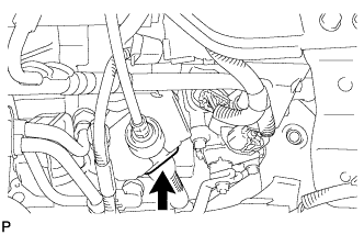
Install the park/neutral position switch to the manual valve shaft.
-
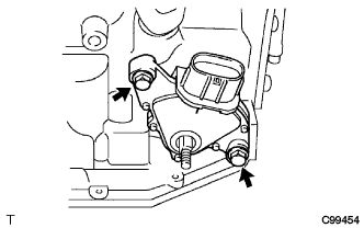
Temporarily install the 2 bolts.
-
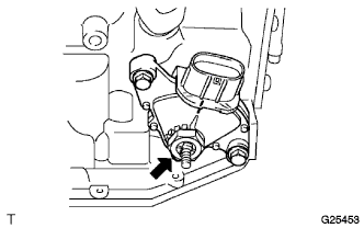
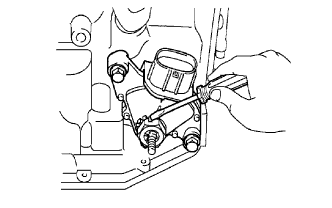
Place a new lock plate and tighten the nut.
- Torque:
- 6.9 N*m { 70 kgf*cm, 61 in.*lbf }
-
Temporarily install the control shaft lever.
-
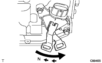
Turn the lever counterclockwise until it stops and then turn it clockwise 2 notches.
-
Remove the control shaft lever.
-
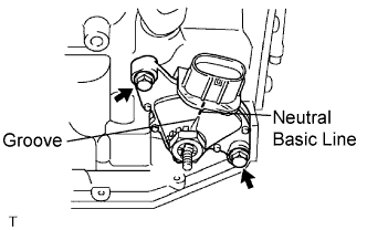
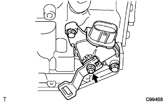
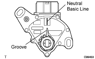
Align the groove with the neutral basic line.
-
Hold the switch in position and tighten the 2 bolts.
- Torque:
- 5.4 N*m { 55 kgf*cm, 48 in.*lbf }
-
Using a screwdriver, bend the tabs of the lock plate.
-
Install the control shaft lever washer and the nut.
- Torque:
- 13 N*m { 130 kgf*cm, 9 ft.*lbf }
-
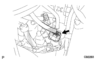
Connect the park/neutral position switch connector.
-
-
CONNECT TRANSMISSION CONTROL CABLE ASSEMBLY
-
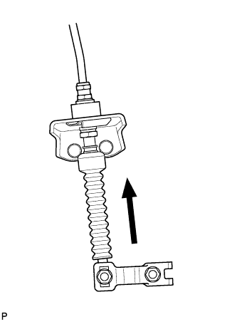
Connect the control cable to the control shaft lever with the nut.
- Torque:
- 15 N*m { 153 kgf*cm, 11 ft.*lbf }
-
Install the control cable to the bracket with a new clip.
-
-
ADJUST PARK/NEUTRAL POSITION SWITCH ASSEMBLY
-
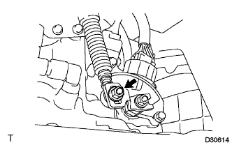
Loosen the 2 bolts of the park/neutral position switch and move the shift lever to the N position.
-
Align the groove with the neutral basic line.
-
Hold the switch in position and tighten the 2 bolts.
- Torque:
- 5.4 N*m { 55 kgf*cm, 48 in.*lbf }
-
After adjustment, inspect the park/neutral position switch assembly operation Click here.
-
-
ADJUST SHIFT LEVER POSITION
-
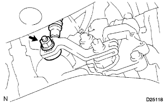
Loosen the nut on the control shaft lever.
-
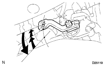
Push the control shaft fully downward.
-
Return the control shaft lever 2 notches to the N position.
-
While pushing the control cable end up with the shift lever in the N position, install it to the control shaft lever with the nut.
- Torque:
- 12 N*m { 122 kgf*cm, 9 ft.*lbf }
Note
-
If the control cable end is excessively pushed up, the shift lever cannot be adjusted.
-
When tightening the nut, confirm that the control cable is properly stretched.
-
Start the engine and make sure that the vehicle moves forward when shifting the lever from the N to the D position and moves rearward when shifting it to the R position.
-
-
INSPECT PARK/NEUTRAL POSITION SWITCH ASSEMBLY OPERATION
-
Apply the parking brake and turn the ignition switch on (IG).
-
Depress the brake pedal and check that the engine starts when the shift lever is set in the N position or P position, but does not start in the other positions.
-
Check that the back-up light illuminates when the shift lever is set in the R position, but does not function in the other positions.
If a malfunction is found, check the park/neutral position switch for continuity.
-
-
INSPECT SHIFT LEVER POSITION
-
When shifting from the P to the R position with the ignition switch on (IG) and the brake pedal depressed, make sure that the shift lever moves smoothly and moves correctly into the position.
-
Start the engine and make sure that the vehicle moves forward when shifting from the N to the D position and moves rearward when shifting to the R position. If operation cannot be done as specified, inspect the park/neutral position switch assembly and check the shift lever assembly installation condition.
-
-
INSTALL AIR CLEANER BRACKET
-
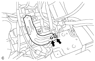
Install the 2 bolts and air cleaner bracket.
- Torque:
- 12 N*m { 123 kgf*cm, 9 ft.*lbf }
-
-
INSTALL AIR CLEANER CASE SUB-ASSEMBLY
-
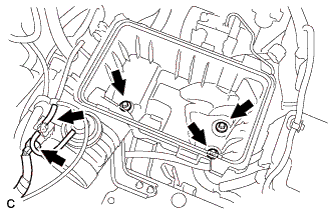
Install the air cleaner case with the 3 bolts.
- Torque:
- 5.0 N*m { 51 kgf*cm, 44 in.*lbf }
-
Connect the hose and connector.
-
-
INSTALL AIR CLEANER FILTER ELEMENT SUB-ASSEMBLY
-
INSTALL AIR CLEANER CAP SUB-ASSEMBLY
-
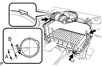
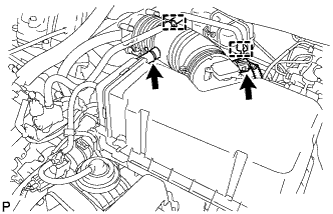
Install the air cleaner filter element, align the groove on the air cleaner hose with the throttle body alignment tab and tighten the clamp as shown in the illustration.
Tech Tips
-
A = 30°
-
B = 11 to 14 mm (0.433 in. to 0.551 in.)
-
-
Install the air cleaner cap with the 2 bolts and clips.
- Torque:
- 5.0 N*m { 51 kgf*cm, 44 in.*lbf }
-
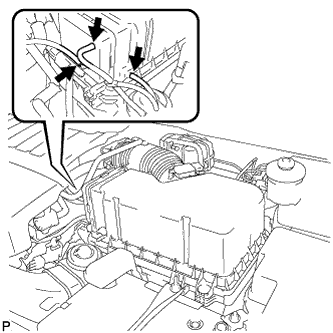
Connect the 3 vacuum hoses.
-
Connect the mass air flow meter connector.
-
Connect the No. 2 ventilation hose and fuel vapor feed hose assembly.
-
-
INSTALL NO. 1 AIR CLEANER INLET
-
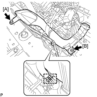
Install the No. 1 air cleaner inlet with the 2 bolts.
- Torque:
- 7.0 N*m { 71 kgf*cm, 62 in.*lbf, [A] }
- Torque:
- 5.0 N*m { 51 kgf*cm, 44 in.*lbf, [B] }
-
Connect the 2 vacuum hoses.
-
-
INSTALL NO. 2 AIR CLEANER INLET
-
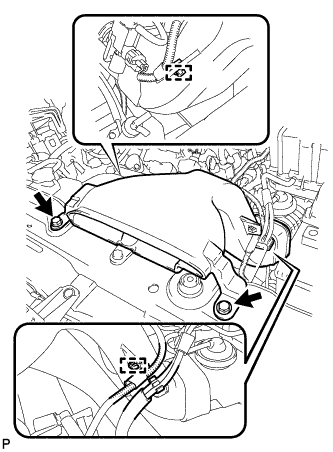
Install the No. 2 air cleaner inlet with the 2 bolts.
- Torque:
- 7.0 N*m { 71 kgf*cm, 62 in.*lbf }
-
Connect the 2 vacuum hoses and harness clamps.
-
-
INSTALL COOL AIR INTAKE DUCT SEAL
-
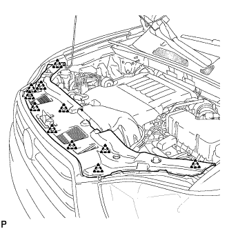
Install the cool air intake duct seal with the 11 clips.
-
-
INSTALL BATTERY
-
Install the battery tray and battery.
-
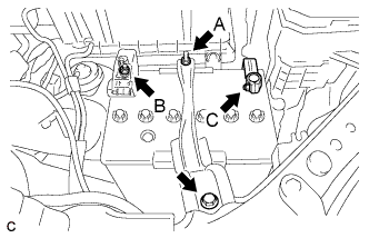
Install the battery clamp with the bolt and nut.
- Torque:
- Bolt
- 5.4 N*m { 55 kgf*cm, 48 in.*lbf }
- Nut A
- 5.4 N*m { 55 kgf*cm, 48 in.*lbf }
- Nut B
- 13 N*m { 131 kgf*cm, 9 ft.*lbf }
- Nut C
- 6.4 N*m { 64 kgf*cm, 57 in.*lbf }
-
Install the positive battery terminal and nut.
-
Connect the negative battery terminal, and tighten the nut.
-
-
CONNECT CABLE TO NEGATIVE BATTERY TERMINAL
Note
When disconnecting the cable, some systems need to be initialized after the cable is reconnected Click here.