| DTC Code | DTC Name |
|---|---|
| P0705 | Transmission Range Sensor Circuit Malfunction (PRNDL Input) |
DESCRIPTION
The park/neutral position switch detects the shift lever position and sends signals to the ECM.
| DTC No. | DTC Detection Condition | Trouble Area |
|---|---|---|
| P0705 | (A) Any 2 or more signals of the following are ON simultaneously (2-trip detection logic)
(B) Any 2 or more signals of the following are ON simultaneously (2-trip detection logic)
(C) All switches are OFF simultaneously for NSW (STAR), P, R, N, D, positions (2-trip detection logic). (D) When any of following conditions for 2 sec. or more in the S position (2-trip detection logic)
|
|
MONITOR DESCRIPTION
These DTCs indicate a problem with the park/neutral position switch and the wire harness in the park/neutral position switch circuit.
The park/neutral position switch detects the shift lever position and sends a signal to the ECM.
For security, the park/neutral position switch detects the shift lever position so that engine can be started only when the shift lever is in the P or N position.
The park/neutral position switch sends a signal to the ECM according to the shift position (P, R, N or D). The ECM determines that there is a problem with the switch or related parts if in receives more than 1 position signal simultaneously. The ECM will turn on the MIL and store the DTC.
INSPECTION PROCEDURE
PROCEDURE
- Click here
CHECK HARNESS AND CONNECTOR (BATTERY - PARK/NEUTRAL POSITION SWITCH)
-
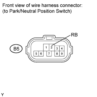
Disconnect the park/neutral position switch connector.
-
Turn the ignition switch on (IG).
-
Measure the voltage according to the value(s) in the table below.
Standard voltage Tester Connection Switch Condition Specified Condition B5-2 (RB) - Body ground Ignition switch on (IG) 11 to 14 V
- OKClick here
- NGClick here
-
- Click here
CHECK HARNESS AND CONNECTOR (OUTPUT SIGNAL)
-
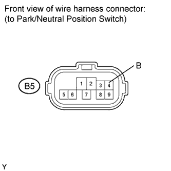
Measure the voltage according to the value(s) in the table below.
Standard voltage Tester Connection Switch Condition Specified Condition B5-4 (B) - Body ground Ignition switch on (IG) 11 to 14 V Result Result Proceed to OK A NG (w/o Smart Entry and Start System) B NG (w/ Smart Entry and Start System) C
-
- Click here
INSPECT PARK/NEUTRAL POSITION SWITCH ASSEMBLY
-
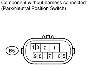
Measure the resistance according to the value(s) in the table below when the shift lever is moved to each position.
Standard resistance Tester Connection Shift Position Specified Condition 4 - 5 P and N Below 1 Ω Except P and N 10 kΩ or higher 2 - 6 P Below 1 Ω Except P 10 kΩ or higher 2 - 1 R Below 1 Ω Except R 10 kΩ or higher 2 - 9 N Below 1 Ω Except N 10 kΩ or higher 2 - 7 D, S, "+" and "-" Below 1 Ω Except D, S, "+" and "-" 10 kΩ or higher
- OKClick here
- NGClick here
-
- Click here
CHECK HARNESS AND CONNECTOR (BATTERY - SHIFT LOCK CONTROL UNIT ASSEMBLY)
-
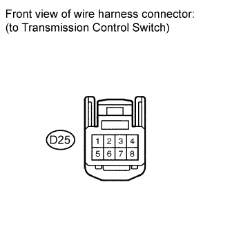
Disconnect the transmission control switch connector of shift lock control unit assembly.
-
Measure the voltage according to the value(s) in the table below.
Standard voltage Tester Connection Switch Condition Specified Condition 3 - Body ground Ignition switch on (IG) 11 to 14 V Ignition switch off Below 1 V
- OKClick here
- NGClick here
-
- Click here
INSPECT SHIFT LOCK CONTROL UNIT ASSEMBLY
-
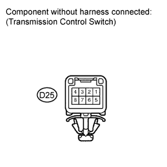
Measure the resistance according to the value(s) in the table below when the shift lever is moved to each position.
Standard resistance Tester Connection Shift Position Specified Condition 3 - 7 S, "+" and "-" Below 1 Ω Except S, "+" and "-" 10 kΩ or higher Result Result Proceed to OK A NG B
-
- Click here
CHECK HARNESS AND CONNECTOR (SHIFT LOCK CONTROL UNIT ASSEMBLY - ECM)
-
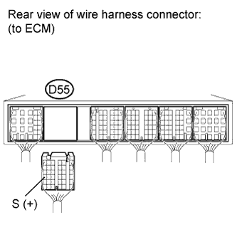
Connect the transmission control switch connector of shift lock control unit assembly.
-
Disconnect the ECM connector.
-
Measure the voltage according to the value(s) in the table below when the shift lever is moved to each position.
Standard voltage Tester Connection Shift Position Specified Condition D55-24 (S) - Body ground S, "+" and "-" 11 to 14 V Except S, "+" and "-" Below 1 V
- OKClick here
- NGClick here
-
- Click here
CHECK HARNESS AND CONNECTOR (PARK/NEUTRAL POSITION SWITCH - ECM)
-
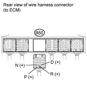
Connect the park/neutral position switch connector.
-
Measure the voltage according to the value(s) in the table below when the shift lever is moved to each position.
Standard voltage Tester Connection Shift Position Specified Condition B50-35 (P) - Body ground P 11 to 14 V Except P Below 1 V B50-29 (N) - Body ground N 11 to 14 V Except N Below 1 V B50-28 (R) - Body ground R 11 to 14 V*
Except R Below 1 V B50-27 (D) - Body ground D and S 11 to 14 V Except D and S Below 1 V Tip:*: The voltage will drop slightly due to lighting up of the back up light.
- OKClick here
- NGClick here
-
- Click here
CHECK HARNESS AND CONNECTOR (PARK/NEUTRAL POSITION SWITCH - ECM)
-
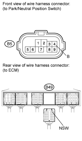
Turn the ignition switch off.
-
Disconnect the ECM connector.
-
Measure the resistance according to the value(s) in the table below.
Standard resistance (Check for open) Tester Connection Condition Specified Condition B5-4 (B) - B49-2 (NSW) Always Below 1 Ω Standard resistance (Check for short) Tester Connection Condition Specified Condition B5-4 (B) or B49-2 (NSW) - Body ground Always 10 kΩ or higher
- OKClick here
- NGClick here
-
- Click here
REPLACE ECM (for 2GR-FE)Click here
- Click here
REPAIR OR REPLACE HARNESS OR CONNECTOR
- Click here
CHECK CRANKING HOLDING FUNCTION CIRCUIT (for 2GR-FE)Click here
- Click here
REPLACE PARK/NEUTRAL POSITION SWITCH ASSEMBLYClick here
- Click here
REPLACE SHIFT LOCK CONTROL UNIT ASSEMBLYClick here