UNDERDRIVE CLUTCH REASSEMBLY
-
INSTALL UNDERDRIVE CLUTCH DRUM O-RING
-
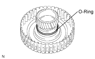
Coat a new O-ring with ATF and install it to the underdrive clutch drum.
Note
Make sure that the O-ring is not twisted or pinched.
-
-
INSTALL UNDERDRIVE CLUTCH PISTON SET
-
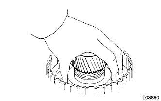
Coat the underdrive clutch piston with ATF, and install it to the underdrive clutch piston drum.
Note
-
Be careful not to damage the O-ring.
-
Be careful not to damage the lip of the piston.
-
-
-
INSTALL UNDERDRIVE CLUTCH RETURN SPRING SUB-ASSEMBLY
-
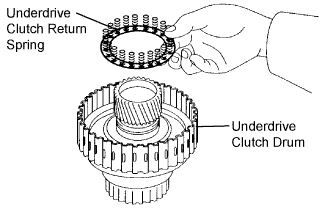
Install the return spring to the underdrive clutch drum.
Note
After installing the spring sub-assembly, check that all of the springs are engaged in the piston correctly.
-
Coat the clutch balancer with ATF.
-
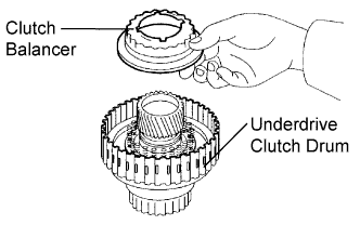
Install the clutch balancer to the underdrive clutch drum.
Note
Be careful not to damage the lip of the clutch balancer.
-
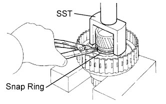
Place SST on the clutch balancer and compress the piston return spring with a press.
- SST
- 09350-32014 ( 09351-32070 )
-
Using a snap ring expander, install the snap ring to the underdrive clutch drum.
-
Be sure that the end gap of the snap ring is not aligned with the spring retainer claw.
Note
-
Stop the press when the spring seat is lowered to the place 1 to 2 mm (0.039 to 0.078 in.) from the snap ring groove. This prevents the spring seat from being deformed.
-
Do not expand the snap ring excessively.
-
-
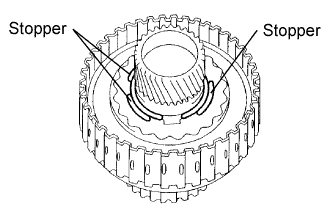
Set the end gap of the snap ring in the underdrive clutch drum as shown in the illustration.
Note
The end gap of the snap ring should not align with any of the stoppers.
-
-
INSTALL NO. 1 UNDERDRIVE CLUTCH DISC
-
Coat the 4 discs with ATF.
-
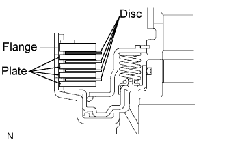
Install the 4 plates, 4 discs, and flange to the underdrive clutch drum.
Note
Make sure that the plates, discs, and flange are installed as shown in the illustration.
-
-
INSTALL NO. 2 UNDERDRIVE CLUTCH FLANGE HOLE SNAP RING
-
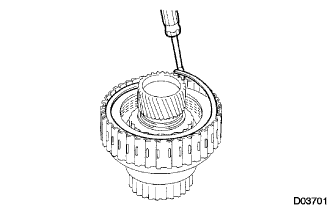
Using a screwdriver, install the No. 2 underdrive clutch flange hole snap ring.
-
Check that the end gap of the snap ring is not aligned with one of the cutouts.
Note
The snap ring should be fully engaged in the groove of the drum.
-
-
INSPECT UNDERDRIVE PACK CLEARANCE
-
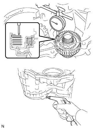
Install the underdrive clutch to the transaxle case.
Note
Be careful not to damage the oil seal rings.
-
Install a dial indicator as shown in the illustration.
-
Measure the underdrive clutch pack clearance while applying and releasing compressed air (392 kPa, 4.0 kgf/cm2, 57 psi).
Pack clearance 1.51 to 1.71 mm (0.0594 to 0.0673 in.) If the pack clearance is not as specified, inspect the discs, plates, and flange.
Tech Tips
There are 5 different thicknesses of flanges available.
Flange thickness: mm (in.) Mark Thickness Mark Thickness 1 3.0 (0.118) 4 3.6 (0.141) 2 3.2 (0.126) 5 3.8 (0.150) 3 3.4 (0.134) - -
-