AUTOMATIC TRANSAXLE UNIT DISASSEMBLY
-
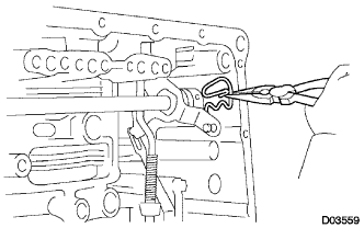
REMOVE PARK/NEUTRAL POSITION SWITCH ASSEMBLY
-
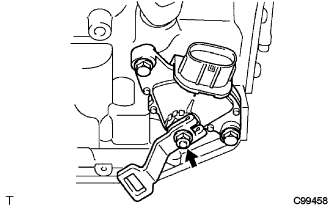
Remove the nut, washer and the control shaft lever.
-
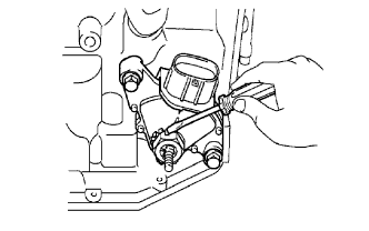
Using a screwdriver, pry up the lock plate.
-
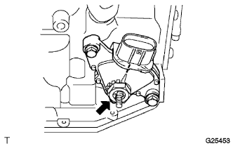
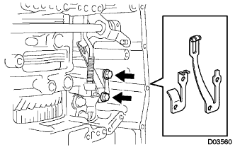
Remove the lock nut and the lock plate.
-
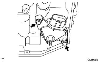
Remove the 2 bolts and pull out the park/neutral position switch.
-
-
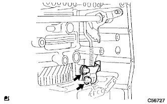
REMOVE BREATHER PLUG HOSE
-
Remove the breather plug hose from the transaxle case.
-
-
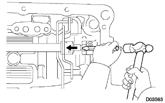
REMOVE OIL COOLER TUBE UNION (INLET OIL COOLER UNION)
-
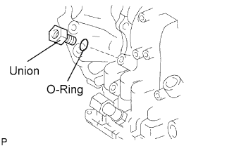
Remove the union.
-
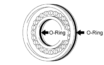
Remove the O-ring from the union.
-
-
REMOVE OIL COOLER TUBE UNION (OUTLET OIL COOLER UNION)
-
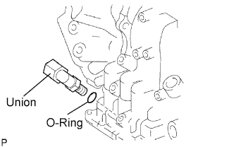
Remove the union.
-
Remove the O-ring from the union.
-
-
REMOVE SPEED SENSOR
-
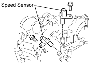
Remove the 2 bolts and the 2 speed sensors from the transaxle assembly.
-
-
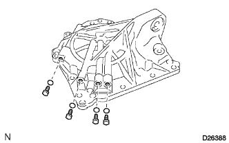
REMOVE NO. 1 TRANSAXLE CASE PLUG
-
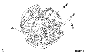
Remove the 4 No. 1 transaxle case plugs from the transaxle case.
-
Remove the 4 O-rings from the 4 No. 1 transaxle case plugs.
-
-
SUPPORT AUTOMATIC TRANSAXLE ASSEMBLY
-
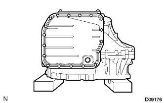
Support the transaxle assembly on wooden blocks.
-
-
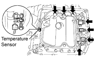
REMOVE AUTOMATIC TRANSAXLE OIL PAN SUB-ASSEMBLY
-
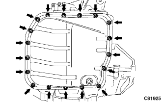
Remove the 18 bolts, oil pan, and gasket.
-
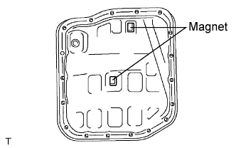
Remove the 2 magnets from the oil pan.
-
-
INSPECT TRANSMISSION OIL CLEANER MAGNET
-
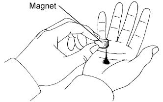
Remove the magnets and use them to collect any steel chips. Examine the chips and particles in the pan and on the magnet to determine what type of wear has occurred in the transaxle:
Result Steel (magnetic) Wear of the bearing, gear, and plate Brass (non-magnetic) Wear of the bushing
-
-
DISCONNECT TRANSMISSION WIRE
-
Remove the 7 connectors from the shift solenoid valves.
-
Remove the bolt, lock plate, and temperature sensor.
-
-
REMOVE TRANSMISSION WIRE
-
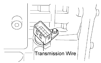
Remove the bolt and transmission wire from the transaxle case.
-
-
REMOVE VALVE BODY OIL STRAINER ASSEMBLY
-
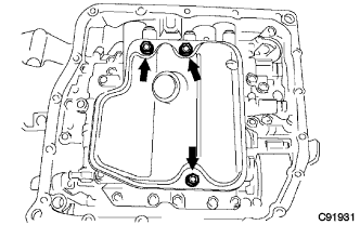
Remove the 3 bolts and oil strainer.
-
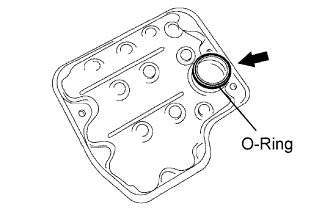
Remove the O-ring from the oil strainer.
-
-
REMOVE TRANSMISSION VALVE BODY ASSEMBLY
-
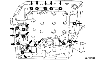
Support the valve body assembly and remove the 17 bolts and valve body assembly.
-
-
REMOVE NO. 1 GOVERNOR APPLY GASKET
-
Remove the No. 1 governor apply gasket from the transaxle case.
-
-
REMOVE TRANSAXLE CASE 2ND BRAKE GASKET
-
Remove the transaxle case 2nd brake gasket from the transaxle case.
-
-
REMOVE BRAKE DRUM GASKET
-
Remove the brake drum gasket from the transaxle case.
-
-
REMOVE CHECK BALL BODY
-
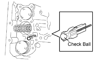
Remove the check ball body and spring from the transaxle case.
-
-
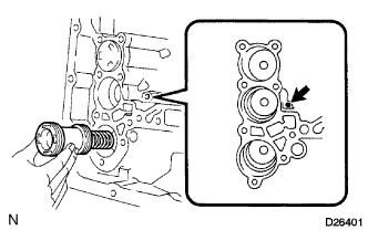
REMOVE C-3 ACCUMULATOR PISTON
-
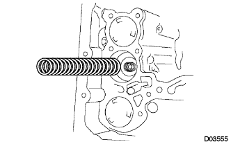
Remove the spring from the C-3 accumulator piston.
-
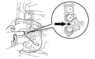
Apply compressed air (392 kPa, 4.0 kgf/cm2, 57 psi) to the oil hole and remove the C-3 accumulator piston.
Note
-
Applying compressed air may cause the piston to jump-out. When removing the piston, hold it using a shop rag or a piece of cloth.
-
Take care not to splash ATF when applying compressed air.
-
-
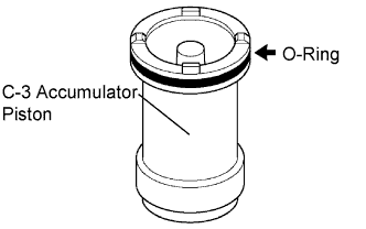
Remove the O-ring from the C-3 accumulator piston.
-
-
REMOVE REVERSE CLUTCH ACCUMULATOR PISTON
-
Apply compressed air (392 kPa, 4.0 kgf/cm2, 57 psi) to the oil hole and remove the reverse accumulator piston and spring.
Note
-
Applying compressed air may cause the piston to jump-out. When removing the piston, hold it using a shop rag or a piece of cloth.
-
Take care not to splash ATF when applying compressed air.
-
-
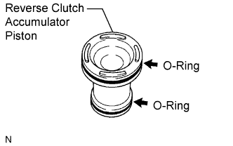
Remove the 2 O-rings from the reverse clutch accumulator piston.
-
-
REMOVE B-3 ACCUMULATOR PISTON
-
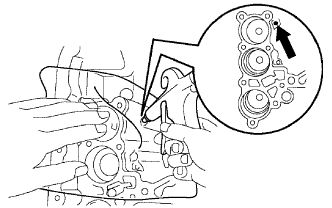
Apply compressed air (392 kPa, 4.0 kgf/cm2, 57 psi) to the oil hole and remove the B-3 accumulator piston and 2 springs.
Note
-
Applying compressed air may cause the piston to jump-out. When removing the piston, hold it using a shop rag or a piece of cloth.
-
Take care not to splash ATF when applying compressed air.
-
-
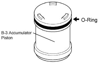
Remove the O-ring from the B-3 accumulator piston.
-
-
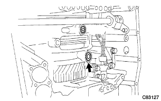
REMOVE MANUAL VALVE LEVER SHAFT RETAINER SPRING
-
Using needle-nose pliers, remove the manual valve lever shaft retainer spring.
-
-
REMOVE MANUAL DETENT SPRING SUB-ASSEMBLY
-
Remove the 2 bolts, the manual detent spring sub-assembly and cover.
-
-
REMOVE PARKING LOCK PAWL BRACKET
-
Remove the 2 bolts and parking lock pawl bracket.
-
-
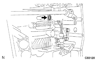
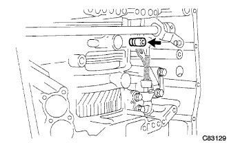
REMOVE MANUAL VALVE LEVER SUB-ASSEMBLY
-
Using a chisel and hammer, cut off and remove the spacer.
-
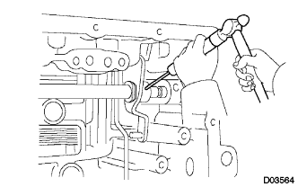
Using a pin punch (φ35 mm) and hammer, drive out the pin.
Tech Tips
Slowly drive out the pin so that it will not fall into the transaxle case.
-
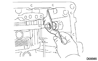
Remove the manual valve lever shaft and manual valve lever.
-
-
REMOVE PARKING LOCK ROD SUB-ASSEMBLY
-
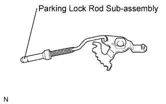
Remove the parking lock rod from the manual valve lever.
-
-
REMOVE MANUAL VALVE LEVER SHAFT OIL SEAL
-
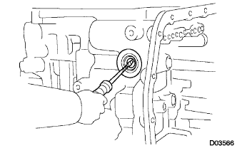
Using a screwdriver, remove the oil seal from the transaxle case.
Note
Do not apply excessive force when removing the oil seal.
-
-
SUPPORT AUTOMATIC TRANSAXLE ASSEMBLY
-
Support the transaxle case with the oil pump side facing up.
-
-
INSPECT INPUT SHAFT END PLAY
-
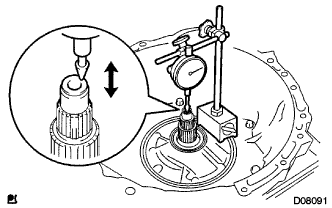
Using a dial indicator, measure the input shaft end play.
End play 0.262 to 1.244 mm (0.0103 to 0.0490 in.) Tech Tips
If the result is not as specified, replace the input shaft or thrust needle roller bearing.
-
-
REMOVE TRANSAXLE HOUSING
-
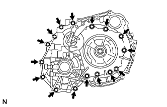
Remove the 16 bolts.
-
Tap on the circumference of the transaxle housing with a plastic hammer to remove the transaxle housing from the transaxle case.
Note
The differential may be accidentally removed when the transaxle housing is removed.
-
-
REMOVE OIL PUMP ASSEMBLY
-
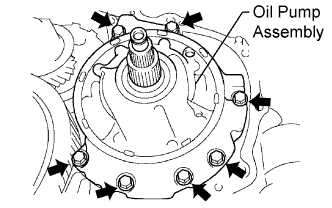
Remove the 7 bolts and oil pump from the transaxle case.
-
-
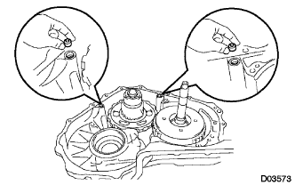
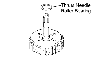
REMOVE THRUST NEEDLE ROLLER BEARING
-
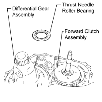
Remove the thrust needle roller bearing from the underdrive planetary gear assembly.
-
-
REMOVE NO. 2 THRUST BEARING UNDERDRIVE RACE
-
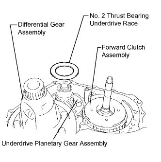
Remove the No. 2 thrust bearing underdrive race from the underdrive planetary gear assembly.
-
-
REMOVE DIFFERENTIAL GEAR ASSEMBLY
-
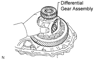
Remove the differential gear assembly from the transaxle case.
-
-
REMOVE OVERDRIVE BRAKE GASKET
-
Remove the 2 overdrive brake gaskets from the transaxle case.
-
-
REMOVE FORWARD CLUTCH ASSEMBLY
-
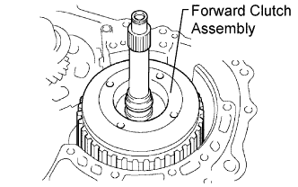
Remove the forward clutch assembly from the transaxle case.
-
Remove the thrust needle roller bearing from the forward clutch.
-
-
REMOVE MULTIPLE DISC CLUTCH HUB
-
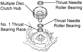
Remove the 2 thrust needle roller bearings, multiple disc clutch hub, and No. 1 thrust bearing race.
-
-
INSPECT MULTIPLE DISC CLUTCH HUB
-
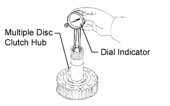
Using a dial indicator, measure the inside diameter of the forward clutch hub bushing.
Standard inside diameter 23.025 to 23.046 mm (0.9065 to 0.9073 in.) Maximum inside diameter 23.09 mm (0.9091 in.) Note
-
Check the contact surface of the bushing in the direct clutch shaft. If any scratch or discoloration is found, replace the direct clutch sub-assembly with a new one.
If the inside diameter is greater than the maximum, replace the forward clutch hub with a new one.
-
-
-
REMOVE UNDERDRIVE PLANETARY GEAR ASSEMBLY
-
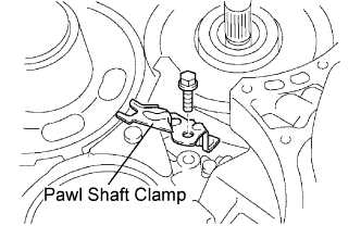
Remove the bolt and pawl shaft clamp.
-
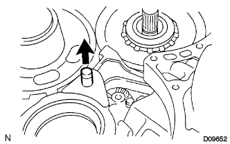
Remove the parking lock pawl shaft.
-
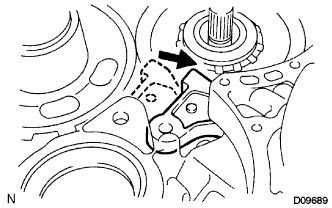
Push the parking lock pawl.
Tech Tips
Failure to do this will cause interference when the underdrive planetary gear is removed.
-
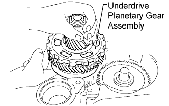
Remove the underdrive planetary gear assembly from the transaxle case.
Note
Be careful so that the underdrive planetary gear assembly will not fall off.
-
-
REMOVE PARKING LOCK PAWL
-
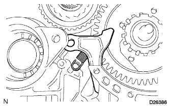
Remove the spring, pawl pin, and parking lock pawl.
-
-
REMOVE UNDERDRIVE CLUTCH ASSEMBLY
-
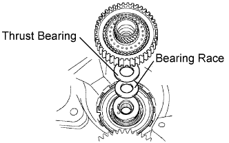
Remove the underdrive clutch assembly, thrust bearing, and bearing race from the transaxle case.
-
-
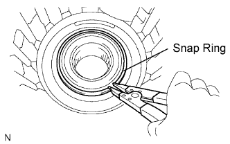
REMOVE UNDERDRIVE ONE-WAY CLUTCH ASSEMBLY
-
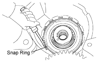
Using a screwdriver, remove the snap ring from the transaxle case.
Note
Do not apply excessive force when removing the snap ring.
-
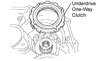
Remove the underdrive one-way clutch from the transaxle case.
-
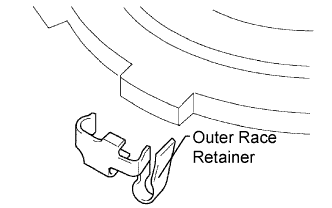
Remove the outer race retainer from the one-way clutch.
-
-
REMOVE NO. 2 UNDERDRIVE CLUTCH DISC
-
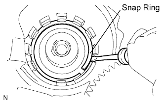
Using a screwdriver, remove the snap ring.
Note
Do not apply excessive force when removing the snap ring.
-
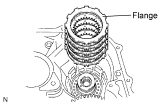
Remove the flange, 4 discs, and 4 plates from the transaxle case.
-
-
INSPECT NO. 2 UNDERDRIVE CLUTCH DISC
-
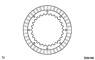
Check if the sliding surfaces of the disc, plate, and flange are worn or burnt.
If necessary, replace them.
Note
-
If the lining of the disc comes off or discolors, or if a part of the groove is worn, replace all discs.
-
Before installing new discs, immerse them in ATF for at least 15 minutes.
-
-
-
REMOVE TRANSAXLE REAR COVER SUB-ASSEMBLY
-

Remove the 11 bolts.
-
Tap on the circumference of the rear cover with a plastic hammer to remove the transaxle rear cover from the transaxle case.
-
-
REMOVE NO. 1 TRANSAXLE CASE PLUG
-
Remove the 4 No. 1 transaxle case plugs from the transaxle rear cover.
-
Remove the 4 No. 1 O-rings from the 4 transaxle case plugs.
-
-
REMOVE REAR CLUTCH OIL SEAL RING OUTER
-
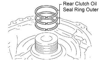
Remove the 3 rear clutch oil seal rings from the transaxle rear cover.
-
-
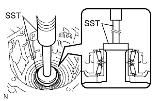
REMOVE NEEDLE ROLLER BEARING
-
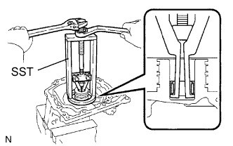
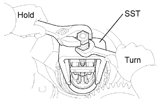
Using SST, remove the needle roller bearing from the transaxle rear cover.
- SST
- 09387-00041 ( 09387-01021, 09387-01030, 09387-01040 )
-
-
REMOVE NO. 1 GOVERNOR APPLY GASKET
-
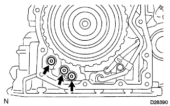
Using a screwdriver, remove the 3 apply gaskets.
-
-
REMOVE BRAKE APPLY TUBE
-
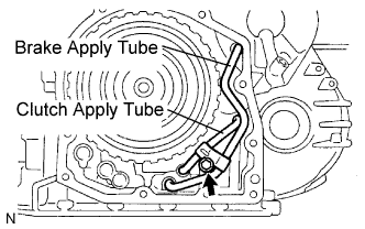
Remove the bolt, clamp, and brake apply tube.
-
Remove the clutch apply tube.
-
Remove the brake apply tube from the clamp.
Note
Do not bend the tubes.
-
-
REMOVE DIRECT CLUTCH ASSEMBLY
-
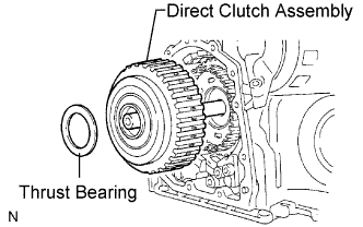
Remove the thrust bearing and the direct clutch assembly from the transaxle case.
-
-
REMOVE OVERDRIVE DIRECT CLUTCH HUB SUB-ASSEMBLY
-
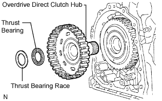
Remove the thrust bearing race, thrust bearing, and overdrive direct clutch hub from the planetary gear assembly.
-
-
INSPECT OVERDRIVE DIRECT CLUTCH DRUM SUB-ASSEMBLY
-
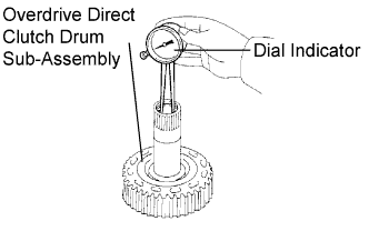
Using a dial indicator, measure the inside diameter of the forward clutch hub bushing.
Standard inside diameter 23.025 to 23.046 mm (0.9065 to 0.9073 in.) Maximum inside diameter 23.09 mm (0.9091 in.) Note
-
Check the contact surface of the bushing in the direct clutch shaft. If any scratch or discoloration is found, replace the direct clutch sub-assembly with a new one.
If the inside diameter is greater than the maximum, replace the forward clutch hub with a new one.
-
-
-
REMOVE REAR PLANETARY SUN GEAR ASSEMBLY
-
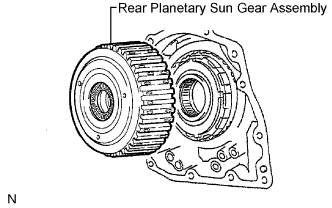
Remove the rear planetary sun gear assembly from the transaxle case.
-
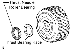
Remove the thrust needle roller bearing and thrust bearing race from the rear planetary sun gear assembly.
-
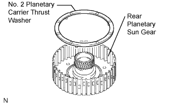
Remove the No. 2 planetary carrier thrust washer from the rear planetary sun gear assembly.
-
-
REMOVE ONE-WAY CLUTCH ASSEMBLY
-
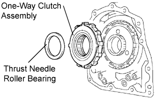
Remove the one-way clutch assembly and the thrust needle roller bearing from the transaxle case.
-
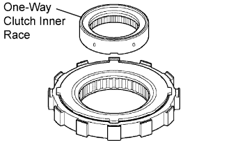
Remove the one-way clutch inner race from the one-way clutch assembly.
-
-
REMOVE ONE-WAY CLUTCH SLEEVE OUTER
-
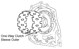
Remove the one-way clutch sleeve outer from the transaxle case.
-
-
REMOVE NO. 1 PLANETARY CARRIER THRUST WASHER
-
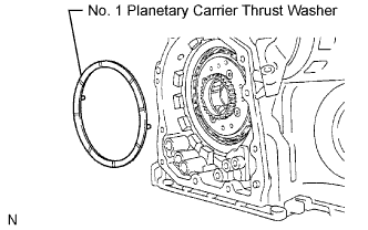
Remove the No. 1 planetary carrier thrust washer from the planetary gear assembly.
-
-
REMOVE 2ND BRAKE CLUTCH DISC
-
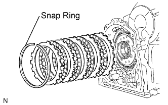
Using a screwdriver, remove the snap ring.
-
Remove the flange, 4 discs, and 4 plates from the transaxle case.
-
-
INSPECT 2ND BRAKE CLUTCH DISC
-
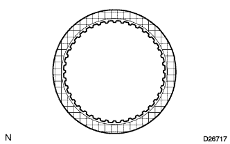
Check if the sliding surface of the disc, plate, and flange are worn or burnt.
If necessary, replace them.
Note
-
If the lining of the disc comes off or discolors, or if a part of the groove is worn, replace all discs.
-
Before installing new discs, immerse them in ATF for at least 15 minutes.
-
-
-
REMOVE 2ND BRAKE PISTON ASSEMBLY
-
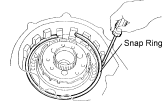
Using a screwdriver, remove the snap ring.
-
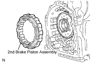
Remove the 2nd brake piston assembly from the transaxle case.
-
-
REMOVE REAR PLANETARY GEAR ASSEMBLY
-
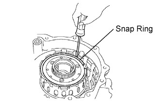
Using a screwdriver, remove the snap ring.
-
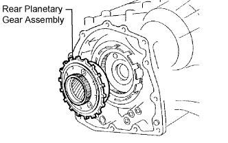
Remove the rear planetary gear assembly from the transaxle case.
-
-
REMOVE INPUT SUN GEAR
-
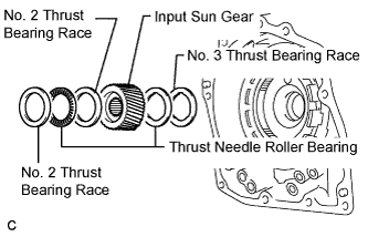
Remove the 2 thrust needle roller bearings, No. 2 thrust bearing race, No. 3 thrust bearing race, and the input sun gear from the transaxle case.
-
-
REMOVE 1ST AND REVERSE BRAKE CLUTCH DISC
-
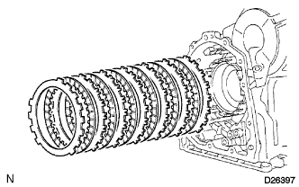
Remove the flange, 6 discs, and 6 plates from the transaxle case.
-
-
INSPECT 1ST AND REVERSE BRAKE CLUTCH DISC
-
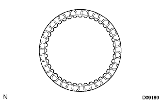
Check if the sliding surface of the disc, plate, and flange are worn or burnt.
If necessary, replace them.
Note
-
If the lining of the disc comes off or discolors, or if a part of the groove is worn, replace all discs.
-
Before installing new discs, immerse them in ATF for at least 15 minutes.
-
-
-
REMOVE FRONT PLANETARY GEAR ASSEMBLY
-
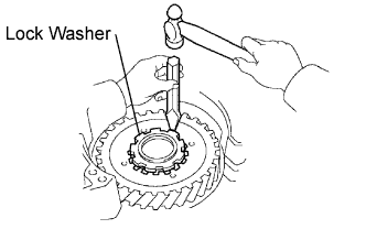
Using a chisel and hammer, unstake the lock washer.
Note
Push down all claws of the washer. Otherwise, SST cannot be fully pressed against the nut, and the nut cannot be loosened.
-
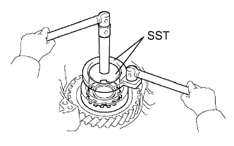
Using SST, remove the nut.
- SST
- 09387-00030
- 09387-00080
-
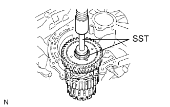
Using SST and a press, remove the front planetary gear assembly from the counter drive gear.
- SST
- 09950-60010 ( 09951-00450 )
- 09950-70010 ( 09951-07100 )
-
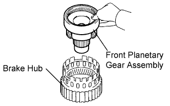
Remove the front planetary gear assembly from the brake hub.
-
-
REMOVE FRONT PLANETARY RING GEAR
-
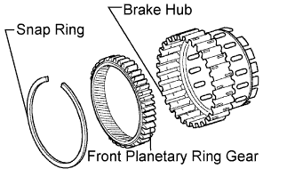
Using a screwdriver, remove the snap ring and front planetary ring gear from the brake hub.
-
-
REMOVE 1ST AND REVERSE BRAKE RETURN SPRING SUB-ASSEMBLY
-
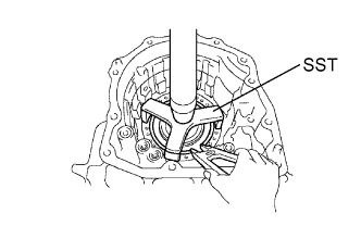
Place SST on the return spring, and compress the return spring with a press.
- SST
- 09387-00070
-
Using a snap ring expander, remove the snap ring.
Note
-
Stop the press when the spring seat is lowered 1 to 2 mm (0.039 to 0.078 in.) from the snap ring groove to prevent the spring seat from being deformed.
-
Do not expand the snap ring excessively.
-
-
-
INSPECT 1ST AND REVERSE BRAKE RETURN SPRING SUB-ASSEMBLY
-
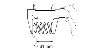
Using vernier calipers, measure the free length of the spring together with the spring seat.
Standard free length 17.61 mm (0.6933 in.) Tech Tips
If the result is not as specified, replace the spring.
-
-
REMOVE 1ST AND REVERSE BRAKE PISTON
-
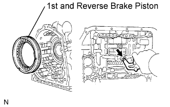
Apply compressed air (392 kPa, 4.0 kgf/cm2, 57 psi) to the transaxle case to remove the 1st and reverse brake piston.
Note
-
Applying compressed air may cause the piston to jump-out. When removing the piston, hold it using a shop rag or a piece of cloth.
-
Take care not to splash ATF when applying compressed air.
-
-
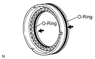
Remove the 2 O-rings from the 1st and reverse brake piston.
-
-
REMOVE COUNTER DRIVE GEAR
-
Using SST and a press, remove the counter drive gear from the transaxle case.
- SST
- 09950-60010 ( 09951-00590 )
- 09950-70010 ( 09951-07100 )
-
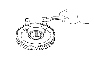
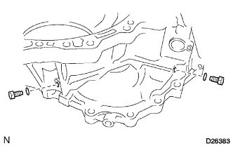
As shown in the illustration, tighten the 2 bolts evenly and make clearance of approx. 20.0 mm (0.787 in.) between the counter drive gear and the inner race.
-
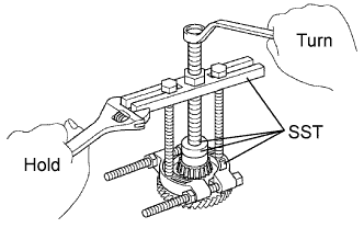
Using SST, remove the tapered roller bearing.
- SST
- 09950-60010 ( 09951-00590 )
- 09950-00020
- 09950-00030
- 09950-40011 ( 09957-04010 )
-
-
REMOVE COUNTER DRIVE GEAR BEARING
-
Using a snap ring expander, remove the snap ring.
-
Using SST and a press, remove the bearing outer race.
- SST
- 09950-60020 ( 09951-00910 )
-
-
REMOVE NO. 2 BREATHER PLUG
-
REMOVE UNDERDRIVE BRAKE RETURN SPRING SUB-ASSEMBLY
-
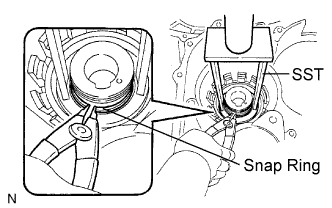
Place SST on the return spring, and compress the return spring with a press.
- SST
- 09387-00020
-
Using a snap ring expander, remove the snap ring.
Note
-
Stop the press when the spring seat is lowered 1 to 2 mm (0.039 to 0.078 in.) from the snap ring groove, to prevent the spring seat from being deformed.
-
Do not expand the snap ring excessively.
-
-
-
INSPECT UNDERDRIVE BRAKE RETURN SPRING SUB-ASSEMBLY
-
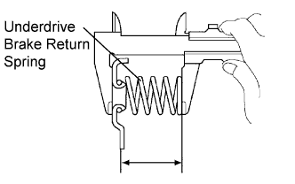
Using vernier calipers, measure the free length of the spring together with the spring seat.
Standard free length 13.24 mm (0.5213 in.) Tech Tips
If the result is not as specified, replace the spring.
-
-
REMOVE UNDERDRIVE BRAKE PISTON
-
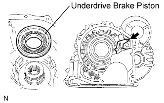
Apply compressed air (392 kPa, 4.0 kgf/cm2, 57 psi) to the transaxle case to remove the underdrive brake piston.
-
Remove the 2 O-rings from the underdrive brake piston.
-
-
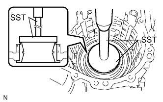
REMOVE NEEDLE ROLLER BEARING
-
Using SST, remove the needle roller bearing from the transaxle case.
- SST
- 09387-00041 ( 09387-01010, 09387-01030, 09387-01040 )
-
-
REMOVE UNDERDRIVE CLUTCH DRUM OIL SEAL RING
-
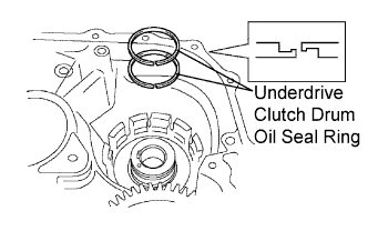
Remove the 2 oil seal rings from the transaxle case.
-
-
REMOVE NO. 1 TRANSAXLE CASE PLUG
-
Remove the 2 No. 1 transaxle case plugs.
-
Remove the 2 O-rings from the 2 No. 1 transaxle case plugs.
-
-
REMOVE UNDERDRIVE CYLINDRICAL ROLLER BEARING
-
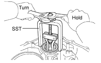
Using SST, remove the underdrive cylindrical roller bearing from the transaxle case.
- SST
- 09514-35011
-
-
REMOVE UNDERDRIVE OUTPUT SHAFT OIL SEAL RING
-
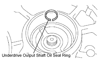
Remove the oil seal ring from the transaxle housing.
-
-
REMOVE DIFFERENTIAL GEAR LUBE APPLY TUBE
-
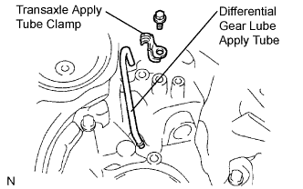
Remove the bolt, transaxle apply tube clamp and differential gear lube apply tube from the transaxle housing.
Note
Do not bend the tubes.
-